Modular Hexagon Platforms
12/18/2021
This idea originally was for my final project for How to Make Almost Anything
Coming up with an idea was kinda hard. I went through a bunch before I landed on one that I wanted to commit to. The following is a fraction of what was in my sticky notes app.
- Robot butterfly
- Robot cubes that can assemble
- Milled metal knob with pot and leds to control stuff
- Open source electric motorized shopping cart
- TVC rocket
- Tape measure bracelet
- Large modular capacitive touch display with big "pixels" that when touched ripple
- Sound balls to echolocate map out room
- Modular hanging automatically irrigated plant boxes
- Low feature smartwatch
- Shopping cart Robot
- Mini saw stop
- Auto move light to keep work illuminated
- Magnet sniffing robot
- Conveyor belt
- Proof of concept robot that can move up stair and maintain level
- Hand robot
- Physical gimbal ball that can point to location in 3D space
- Digital radial arm saw
- Simple Animatronic
- Fire extinguishing robot
- Idk, make scaffolding somehow more techy
- PCB milling + pick and place + reflow oven combo machine
- Acrylic sword with led strip backing
Eventually I decided on a variant of the seventh one. In summary my idea is:
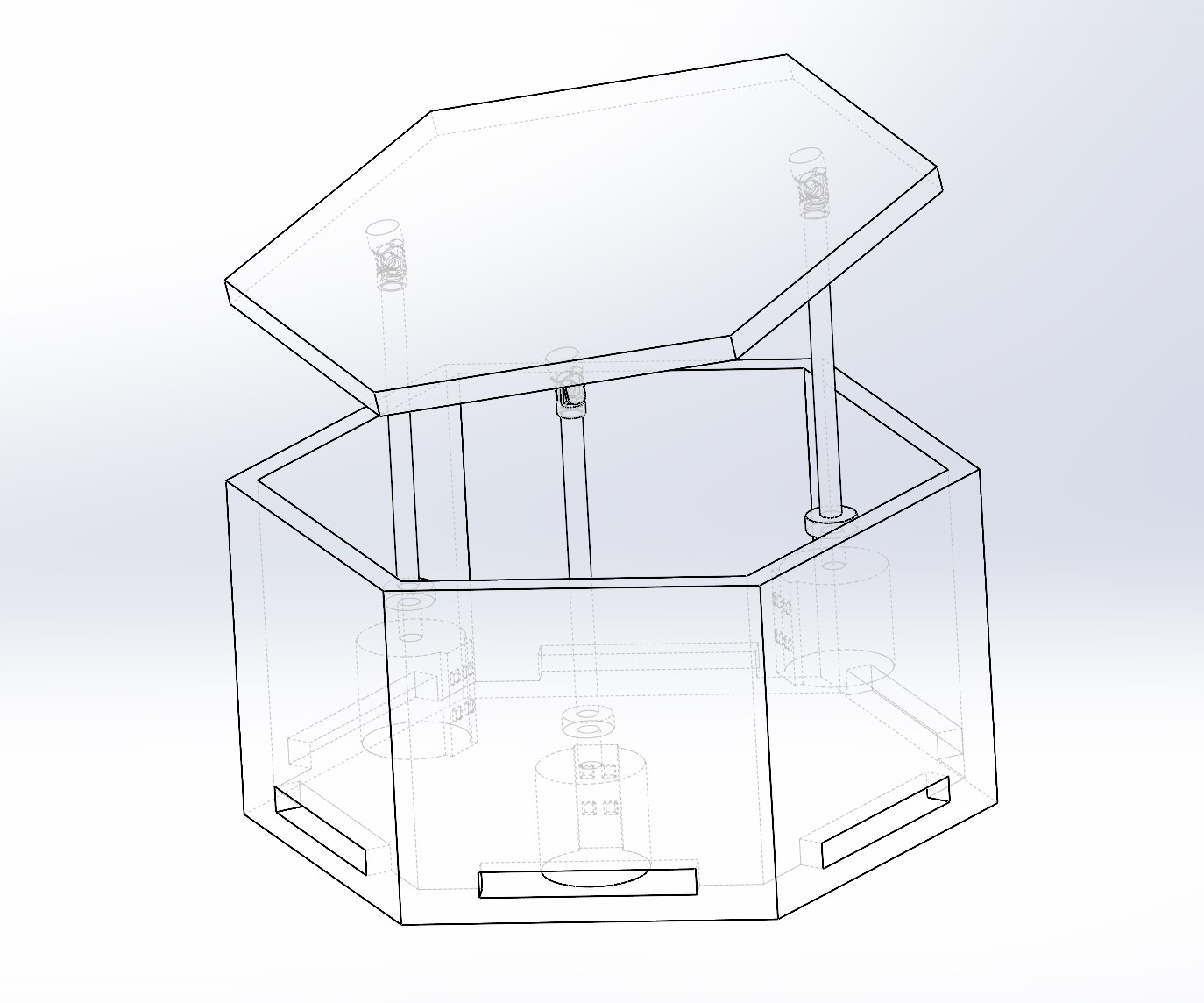
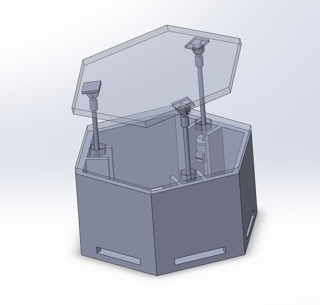
Using a set of three linear actuators arranged in a triangle within a hexagon base, I want to control the orientation of a plane. If I then tesselate these hexagon modules together I can create ripples and waves on the surfaces.
This can be better seen in the following image:
Actuators
Mechanically, this is a pretty simple concept. The only diifficult part is finding/making linear actuators that are small enough, have long enough throw, and cheap enough. There are some options that fit some of those:
Piezo motors would be the absolute perfect thing, only issue is that they are hundreds to thousands of dollars. They are super cool, though
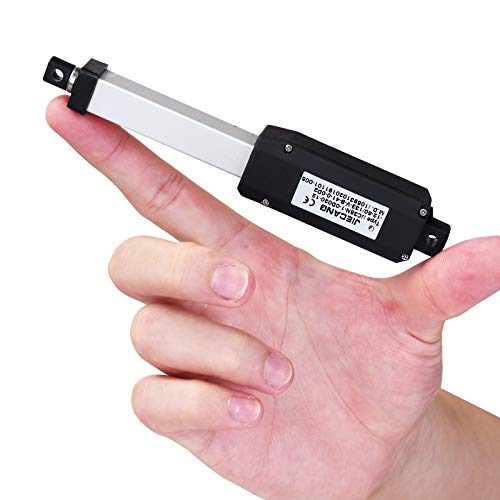
Classic Linear Motors get close, but they are still much bigger and more expensive than I am looking for. Also, I've been unable to find any that work for 5V because running a 12V line complicates things. Finally, I don't really need to lift 60N.
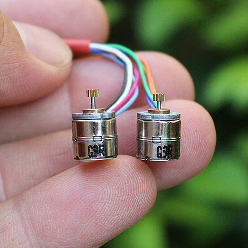
Eventually, I stumbled across these mini stepper motors. They are dirt cheap at less than a dollar a motor too. I could either rack and pinon these or attached them directly to the rod and drive it though a thread to get the vertical motion.
Code
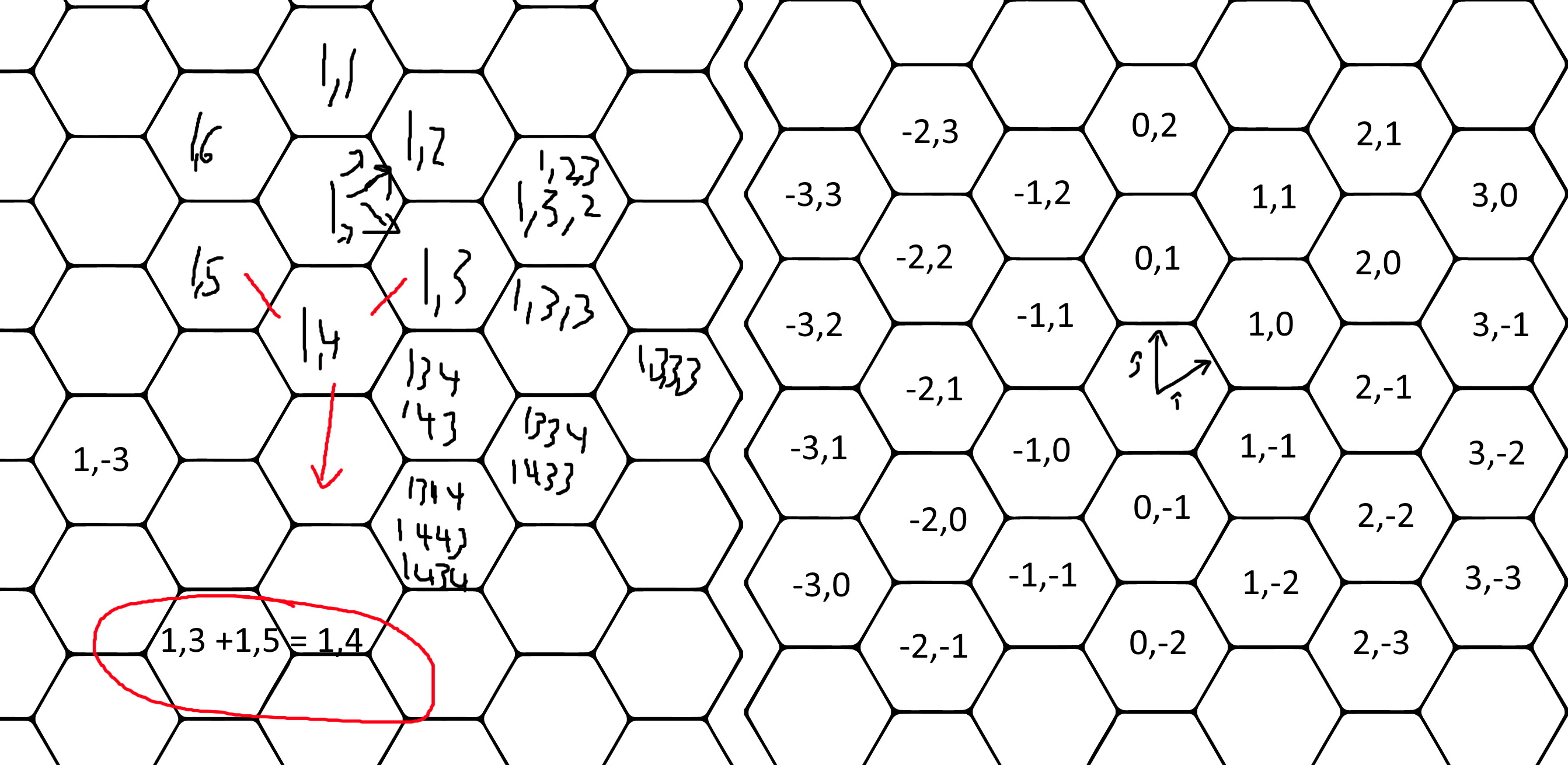
I haven't done it yet, but the code seems like it will be pretty hard. For Serial Communication week, I tried working on figuring out what to do. Ideally, I would be able to talk to a module's six neighbors together. That would requite a full duplex communication. After briefly considering SPI, I decided I should go with six UARTs. Unfortunately, the SAMD21E only has 4 SERCOMs(serial ports), but the SAMD21G has all 6.
I would also want to be able to address each board individually. Because I just got out of a math lecture, I was thinking mathy and make this diagram.
This idea was developed upon during interface and application progrmming week.
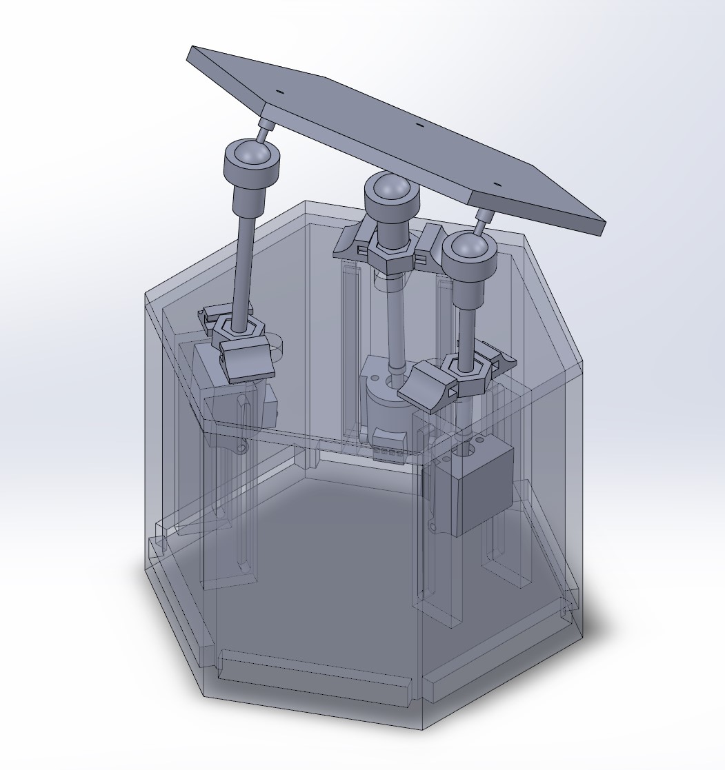
I also updated the CAD because I realized that the worse universal-joint style link wouldn't work. The ball pivots are definitely better but I'n worried about getting a wide enough range of control.
I realized the CAD wasn't working when I applied all the mates because the surface at the top, when it wants to rotate, moves the connection point inwards (obviously).
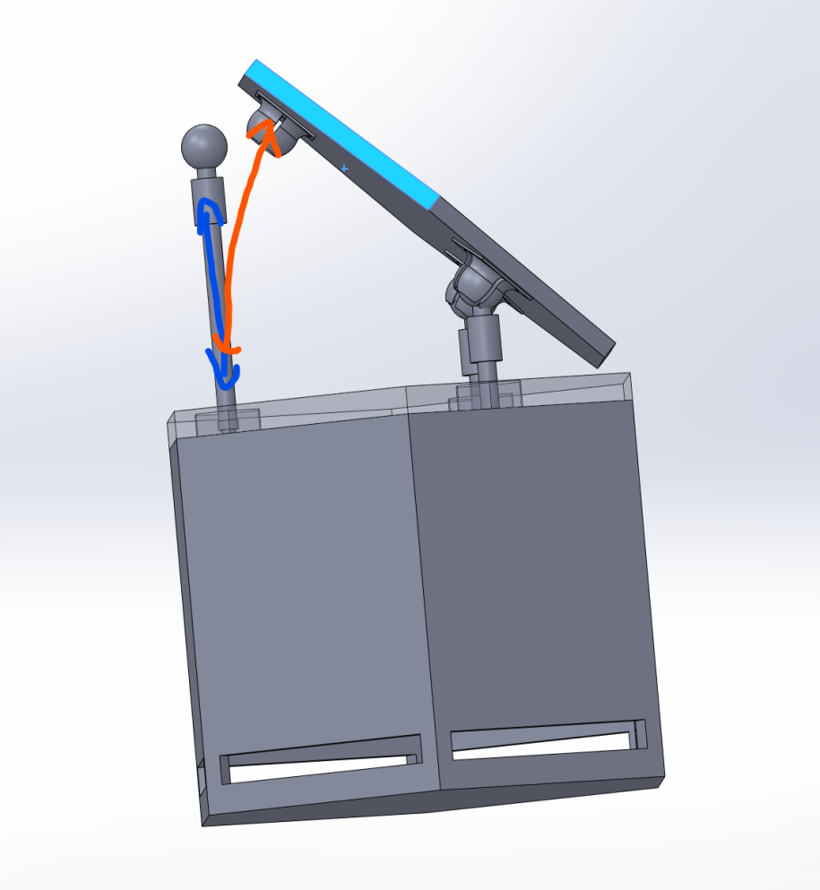
The issue was solved by putting the steppers on rails and allowing them to rotate inwards.
I was also considering using the SAMD21G's pins to drive the stepper motors directly without a stepper driver because it can supply the necessary voltage. However, as Jake informed me, they can only typically supply ~10mA which is much lower than the 0.12A the steppers can draw. Using the SAMD21G would have to be in a future iteration though, because as the deadline drew nearer and nearer, I realized that there wouldn't be enough time to build seven modules, so there was no need for the SAMD21G over the SAMD21E.
Steppers
Once I got my sketchy stepper order, I had to test them. Since I had done steppers with the A4982 in an earlier week, I already knew how I would run the three steppers per module. To start with though I wanted to check that these super cheap little steppers even worked. This consisted of swapping out the sense resistors in the A4982 breakout I had made in output week with one to match the 0.12A the steppers maxxed out at and then just wiring the four stepper wires to the board.
Because the steppers are not just running by themselves, rather with a load, I wanted to check to see if they were strong enough to move what I needed. For this preliminary test, I cut a 4-40 threaded rod to about 35mm long and heatstrinked it onto the stepper's pinion. This coupled the rotation of the stepper to the rod well, but the connection wasn't very stiff, which would prove to be an issue.
Boards
After much deliberation I decided that my system could be implemented with three boards. Each board has a unique function and is a self contained unit.
- Main Board: communicates with the other modules main boards and does any necessary processing.
- Driver Board: contains three A4982 stepper drivers and controls the steppers
- Programming Board: has attachment connectors to talk to main boards, 12V plug to provide power to system, and usb plug to do whatever I want over USB. Eventually, I plan on this becoming an ESP32 board so I can get rid of the USB and go wireless control.
These boards were more complicated to design than the others I had, although I enjoyed the process. I decided to try to use connectors this time so I wouldn't have to rewire anything when I inevitably made a mistake. When making the Driver Board I got stuck was curious to check if Altium's Autoplacer could solve it. I was disappointed to find that it couldn't so I was forced to do it, boosting my ego a tad. The board ended up having 38 vias though, bringing that ego back down.
The symmetric connectors idea on the Main board I stole from Jake's d-pads project. The idea is that you want to be able to plug it in however you want so that means the connection points have to work no matter what orientation. By making the port numbers symmetric across the radially out to centerpoint axis, you get this capability. However, if you're using UARTs to communicate like I am, then Tx goes to Rx and vise versa so they swap places.
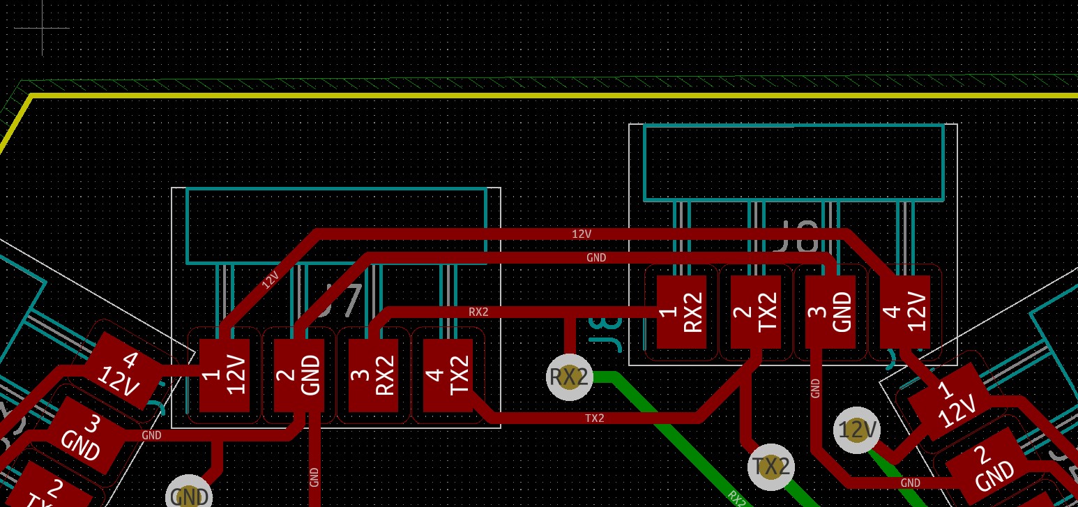
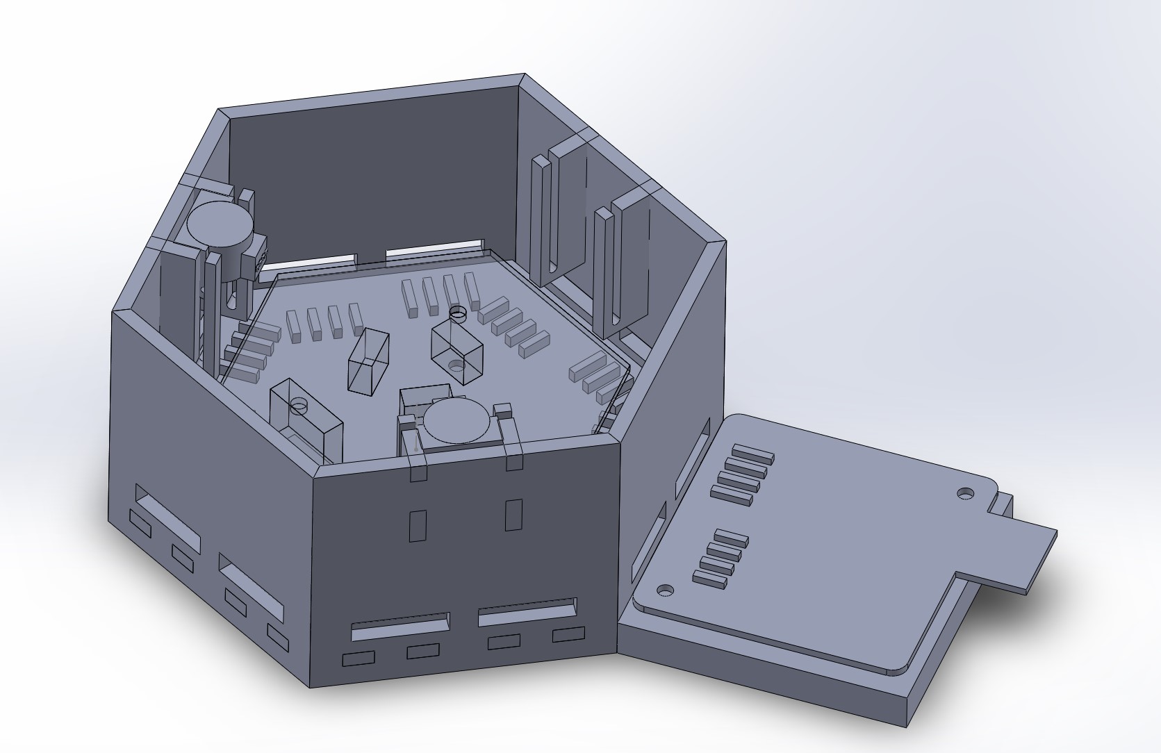
One of the difficulties of using connectors though is that you have to think about their placement. So, first I modeled the board in the Solidworks Assembly so that I could see which size, shape, and placement of components was optimal for each board. I also put a triangle of mounting holes in them so I could form a drone-like stack with them. One I had laid this out, I out convert the CAD board to a DXF and upload it into Kicad to trace over when I actually made the board layout for real.
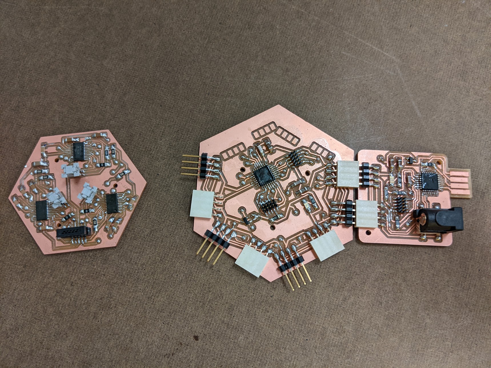
From left to right, Driver board, the Main board, and the Programming Board.
Body
Because I want an individual module to be as cheaply and quickly reproducible, laser cutting the sides was an obvious choice. So I designed my CAD to use finger joints of a parametric thickness so when I would have to change it later on to fit an arbitrary material, I could.
This image shows that design criteria (and the programmer board)
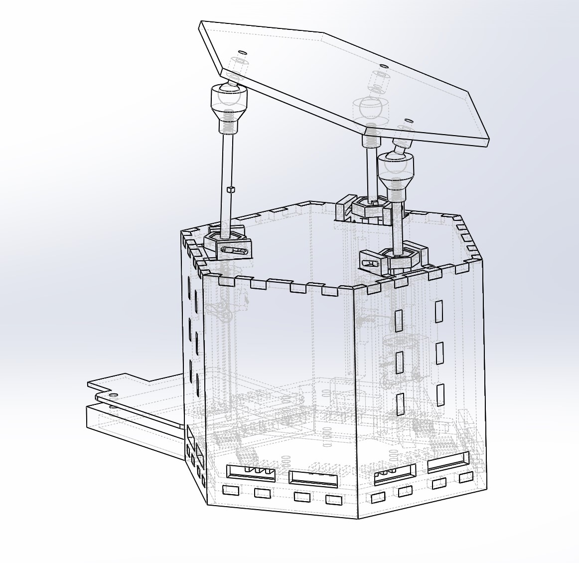
This way, if one day I send the gerbers for the boards to a manufacturing plant, I could theoretically make a whole module in under an hour; which is important if I want to make 10s to 100s of them.
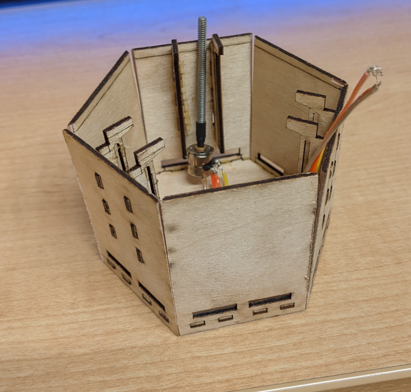
When I cut and assembled the structure out of 1.5mm thick balsa plywood it looked like:
3D printing
The top swivel ball joint, stepper holder, and nut holder for the linear motion have to be 3D printed. I like 3D printing and it's one of the only things we covered in the class that I had experience in beforehand. The stepper and nut holder were pretty staightforward prints. Even though they are small, the geometry is simple, so they print nicely. The swivel ball joint, however, is a print in place. Print in place joints are normally finicky, but way more so when they are as small as mine.
Final Product
I have all the components, I just have to put them together.
Future Considerations
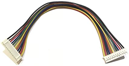
In the future I want to change the connector types to be the JST types. This way it's easier to integrate the steppers into the cable system.
I would also change the programmer board to use and ESP32 instead of a USB port.