Automated Etch A Sketch
05/14/2024
This project has a poster made for it: De Florez Competition Poster
I'd always sucked at drawing anything much more complicated than a rectangle or smiley face on an Etch A Sketch. So, when someone in my lounge in New Vassar bought a full sized Etch A Sketch, a friend and I immediately started joking about making it automated.
This goal could be immediately split up into two separate sub problems:
- Mechanical control of the knobs to rotate to a desired input
- Algorithm to convert an image to knob rotation commands
The Algorithm
This was an interesting problem to solve, as there isn't necessarily a clear way to take in an arbitrary input image and output a continuous line path. I first looked for PNG to SVG converters, but they unfortunately don't really exist. The key issue is shown in the following example, how would you draw a simple pair of stick figures?
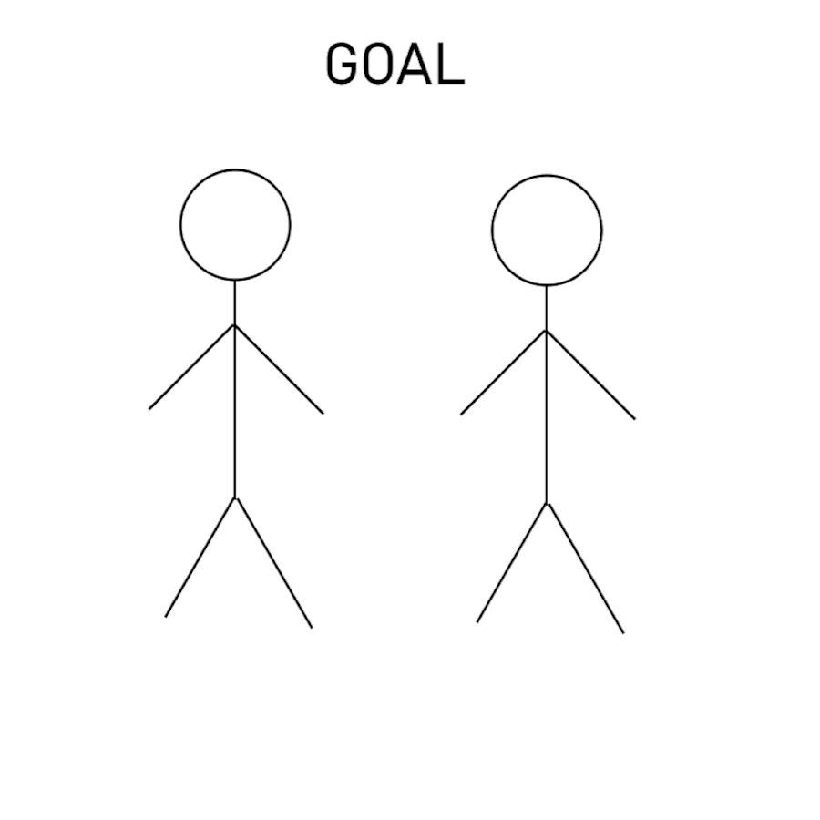
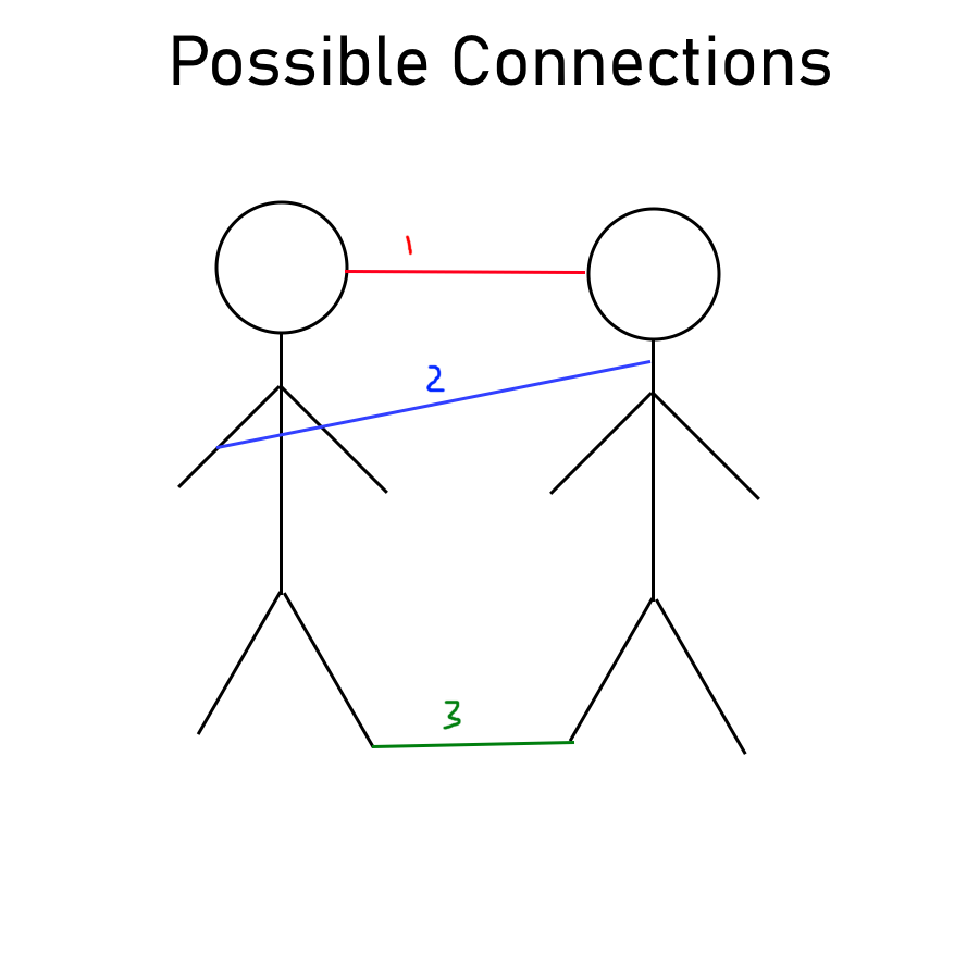
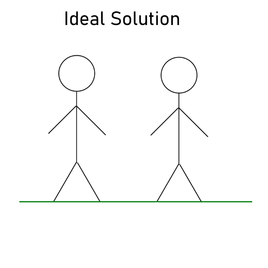
Since Etch-a-Sketches can only draw continuous lines, it is not possible to draw any disjoint objects. So even if someone has a goal as shown on the left, you have to connect the two objects somehow. There are several options:
- Connect the two closest points to each other
- Simply draw a line from where the drawing of one object finishes to where you want to start drawing the other.
- Try to draw a line that is meaningful in the context of the image (like the ground) that connects the two.
But the best solution, as you or I would likely draw, is to draw a line that connects the feet of each of the stick figures together and extends past it to form a complete “ground” line. However, since users might want to draw things other than two stick figures standing next to each other, a ground line connecting the lowest points won't always work. Instead, it would be nice if the image itself already contained connecting lines.
Thanks to generative AI, it can! If I enter the following prompt into OpenAI's Dall-E 3, I get the image below:
Generate a simple image of the following prompt drawn with a single continuous black line without picking up the pen in a line art style. Prompt: Two stick figures next to each other
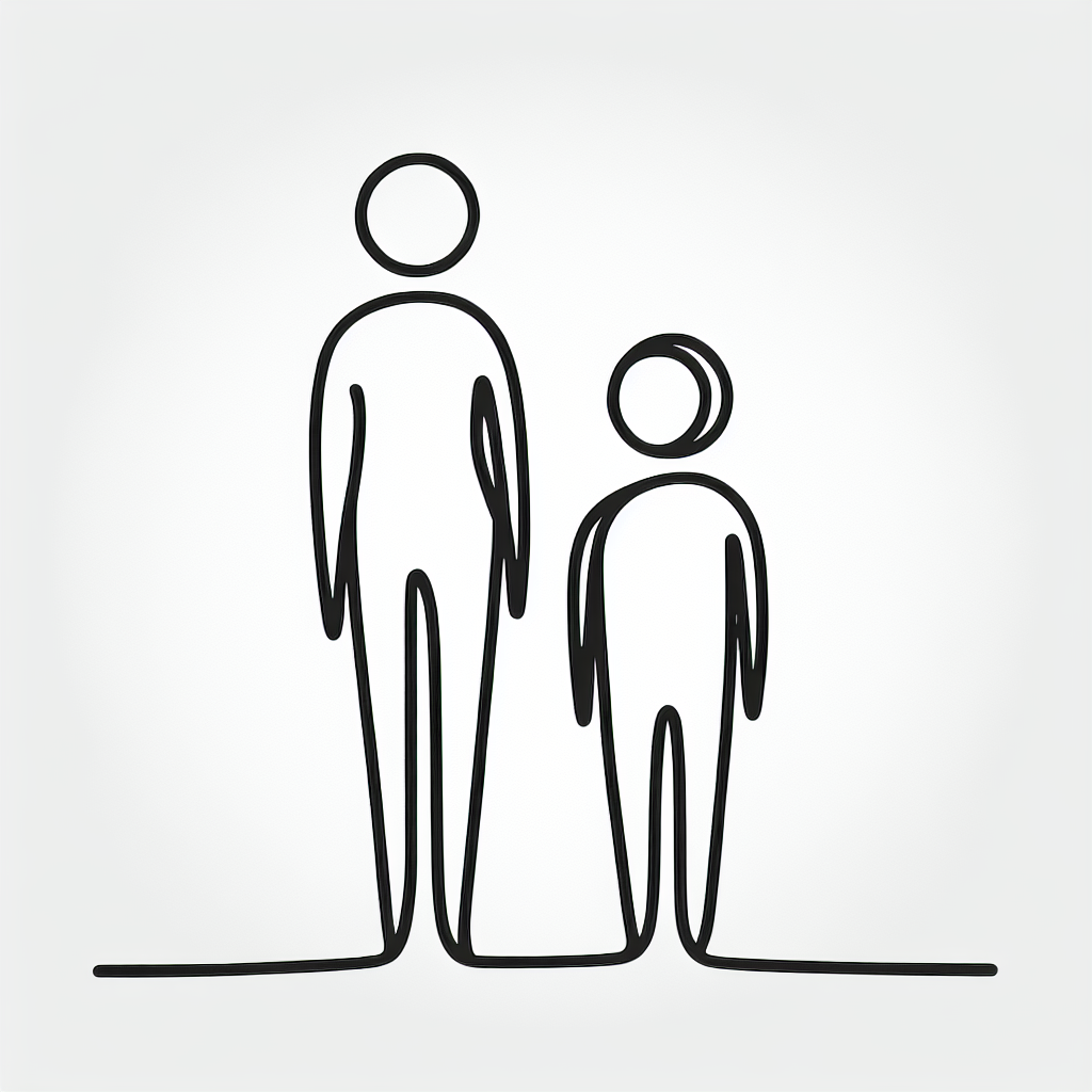
You'll notice that it solves the issue of the bodies not being connected, but adds the issue now of the heads not being connected. So clearly, we will need some kind of shortest-distance algorithm for connecting what Dall-E fails at connecting. After a bit of clean up, namely converting to black and white, downsizing, and removing any artifacts, I can now use standard path finding algorithms to trace out the image.
Full Algorithm:
- Get image from Dall-E from instructions + user prompt
- Convert to Black and White, downscale, find connected components, remove components smaller than 8 pixels.
- Trace by:
- Go from the current point (starts at 0,0) to a point in the next component, minimizing white space traveled through by using Dijkstra's algorithm. Add points traveled through to a path array.
- Depth First Search (DFS) through the component, backtracking with BFS if hitting an end point.
- Repeat until all components are exhausted
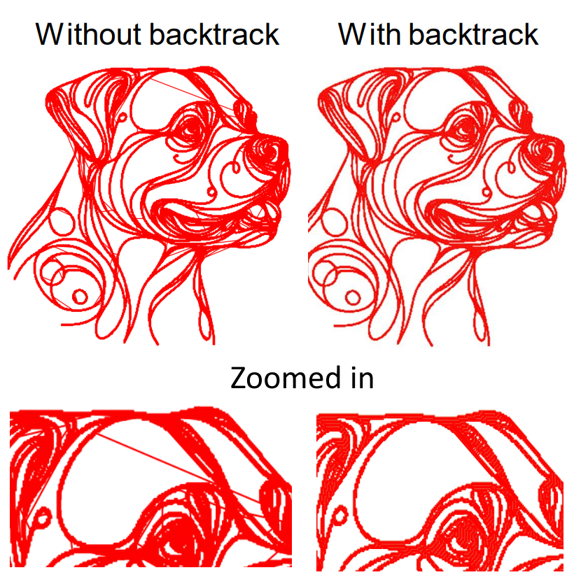
Backtracking is pretty important for clean images. Without it, when the DFS reaches a point where the next point to search from is not adjacent, it would just draw a line directly across to that new point. Instead, backtracking finds the shortest path to that new point by BFS, without traveling through any white space and thus removing any unwanted lines as shown below.
Implementing it took a little bit of trouble, but got it before too long:
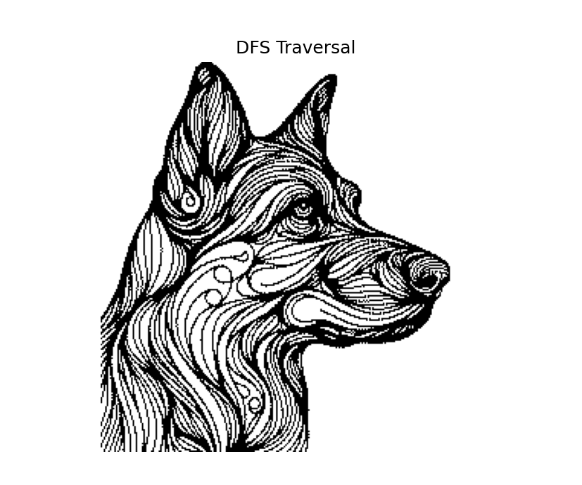
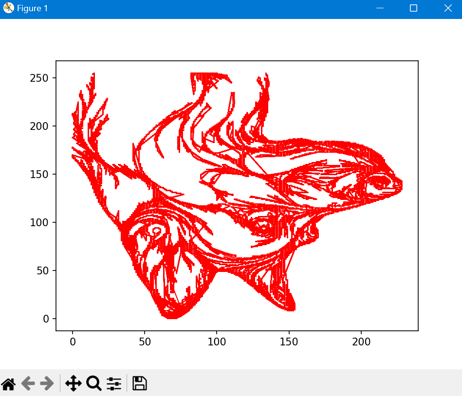
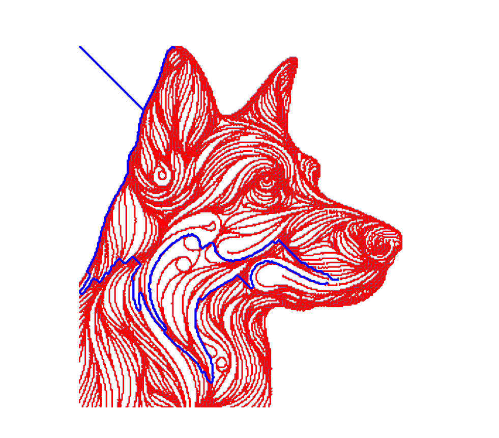
Had issues with:
- Orientation being flipped from what I expected
- Realized that not backtracking was an issue
- Threshold for black white conversion was difficult
- Runtime
Although the algorithm works, and runs the control of the motors simultaneously as it calculates the path, I believe my implementation of it is flawed since it takes ~6 seconds to complete the DFS on a 256x256 image. There is nothing inherently so computation intensive that my well-powered laptop should not be able to run it in under a second.
Mechanical Design
From early on in the design process, I wanted the finished version to look like a marketable product. This meant clean lines, hidden fasteners, sleek form factor, and ease of installation and control. When looking to see if others had built similar projects, we found another example, coincidentally made shortly after we started working on our own. They had mounted the stepper motors directly on top of the knobs, which, while mechanically very straightforward, isn't the most pleasing aesthetically. So, after chatting with my friend Caden, I decided to try doing a belt drive instead and place the motors off the side of the Etch A Sketch.
As with all similar projects, the first step is to accurately CAD the Etch A Sketch to build the design off of. This was a little trickier than normal since the Etch A Sketch had peculiar angles and I wasn't sure how I would attach the mechanism onto the frame.
To test if the theory of belt drive would work, I made a simple model and 3D printed half of it.
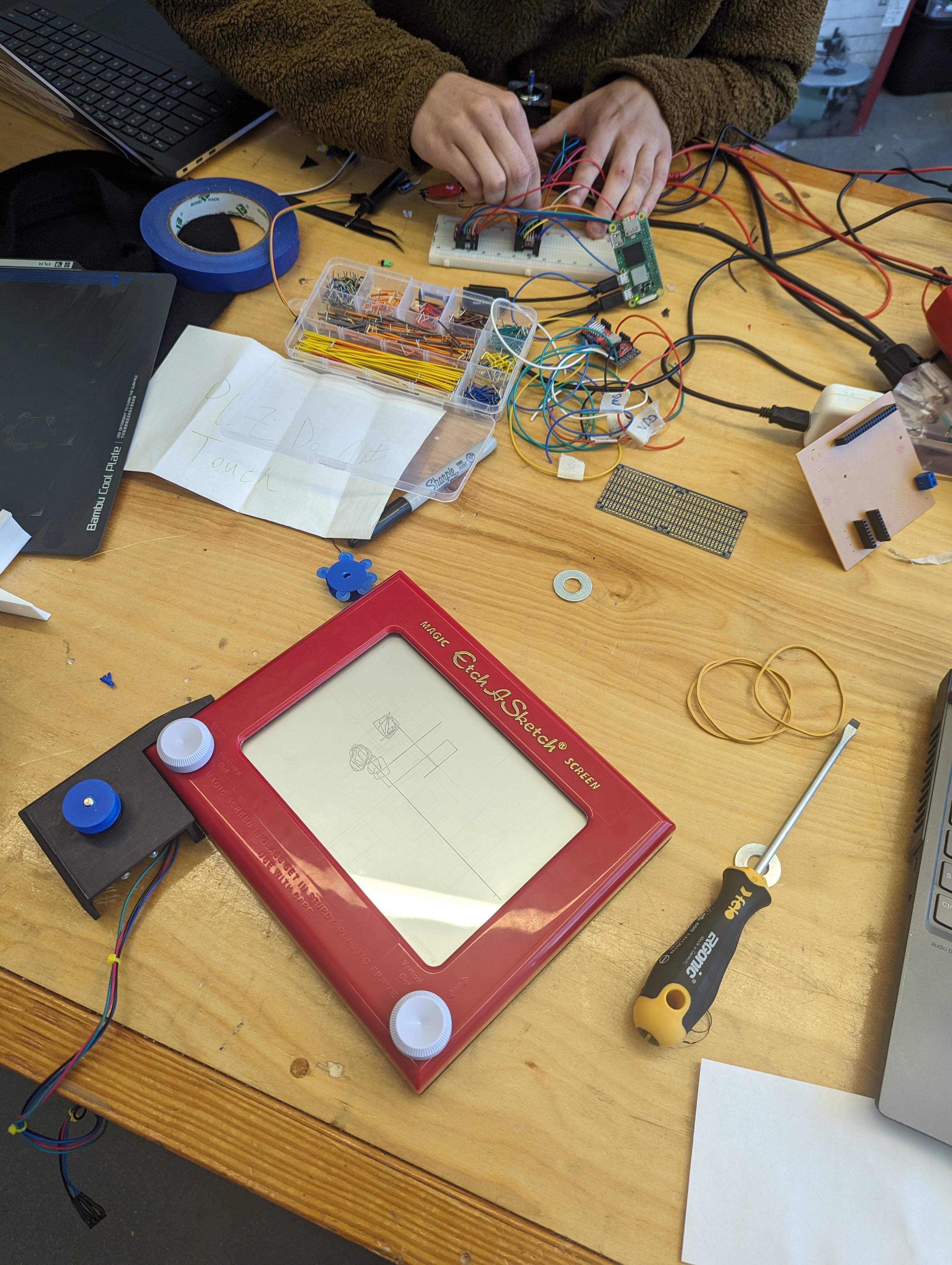
For the belts, I was planning on using rubber bands, since they could self tension and because I had some on hand. However, while testing, it became clear that the rubber bands would take up the motor's torque for a bit before rotating, essentially just acting as gears with really high backlash. So that was a flop. Before I got all bummed about changing ideas though, a friend who was working in the shop mentioned that he had TPU, a flexible 3D-printable filament that I could use to make less stretchy belts.
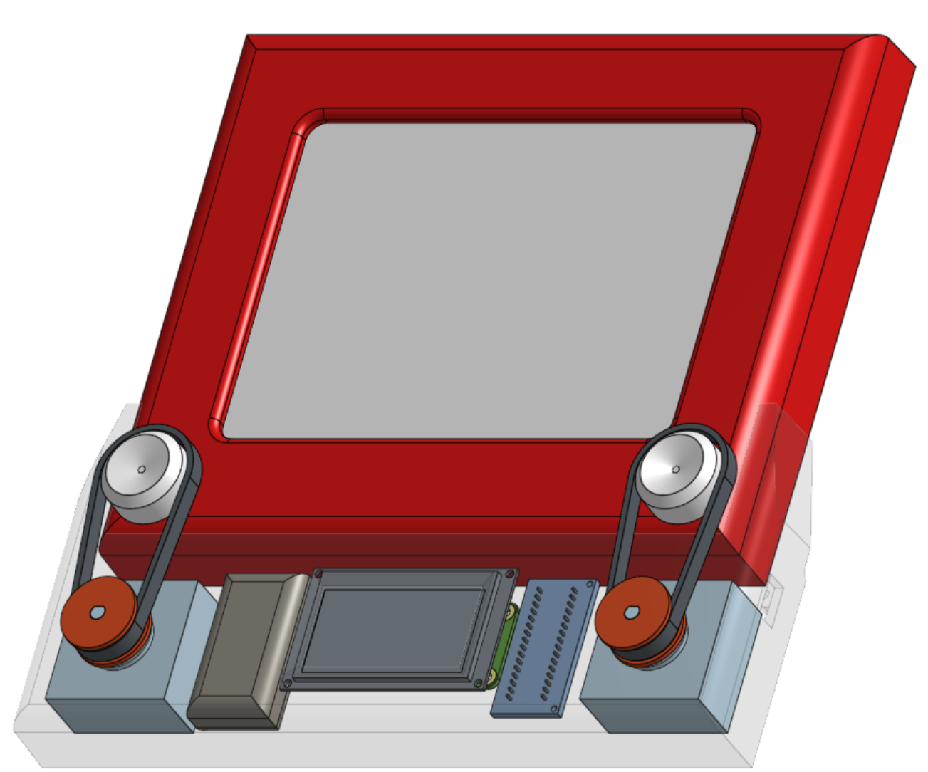
A couple hours later, we ran the test again, and it worked, design saved! After some clean up, I had produced the following cad model. There are no fasteners holding it on to the Etch A Sketch, instead it is held on by the tension of the belts and close tolerances.
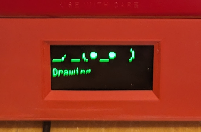
As for the user interface, since we were working with AI image generation, the most natural user input was a text input with a little screen to see what you were typing. JD did a great job making it lifelike by displaying lively animations in each stage of the user process. Low res image:
Finally, here's a component list:
- Raspberry Pi Zero W
- Nema 17 Stepper Motor (2x)
- A4988 Stepper Motor Driver (2x)
- Lipo Battery
- PLA frame
- TPU belts
- PLA pulleys
- Steel back plate
- Mini OLED display
- Lipo Battery
- Mini Bluetooth keyboard
- Etch A Sketch
Integration
Now for the most fun and frustrating part of every project, Integration!! This is probably best told through a series of images.
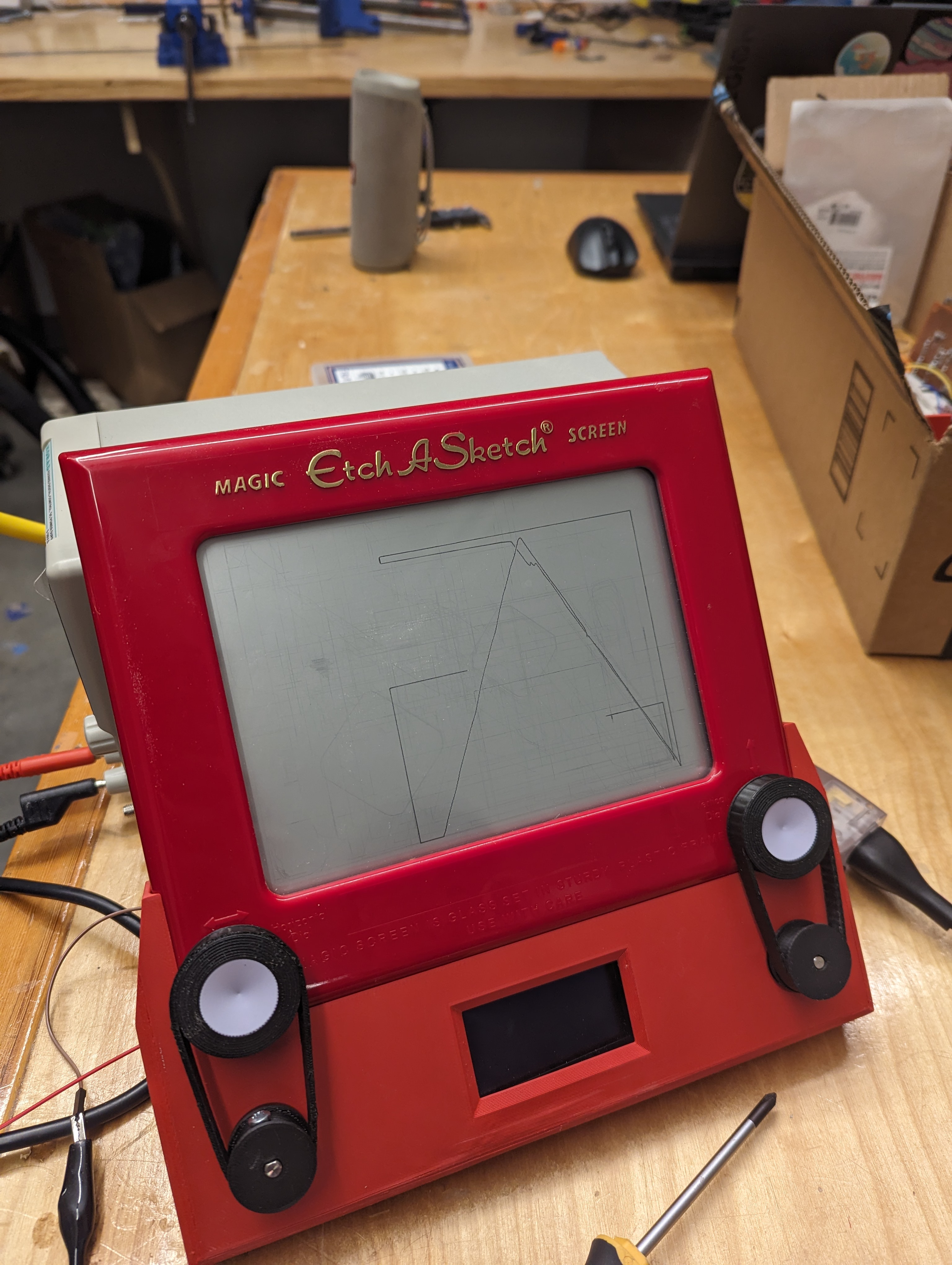
First running of the motor with TPU Belts, just drawing some simple diagonal lines. We had some issues with the lines not being repeatable, so the next test was to draw a series of repeating squares.
Looks pretty good! Turned out the issue was with the code not sequencing the steps correctly. So, we fixed that and tried a the sample dog image.
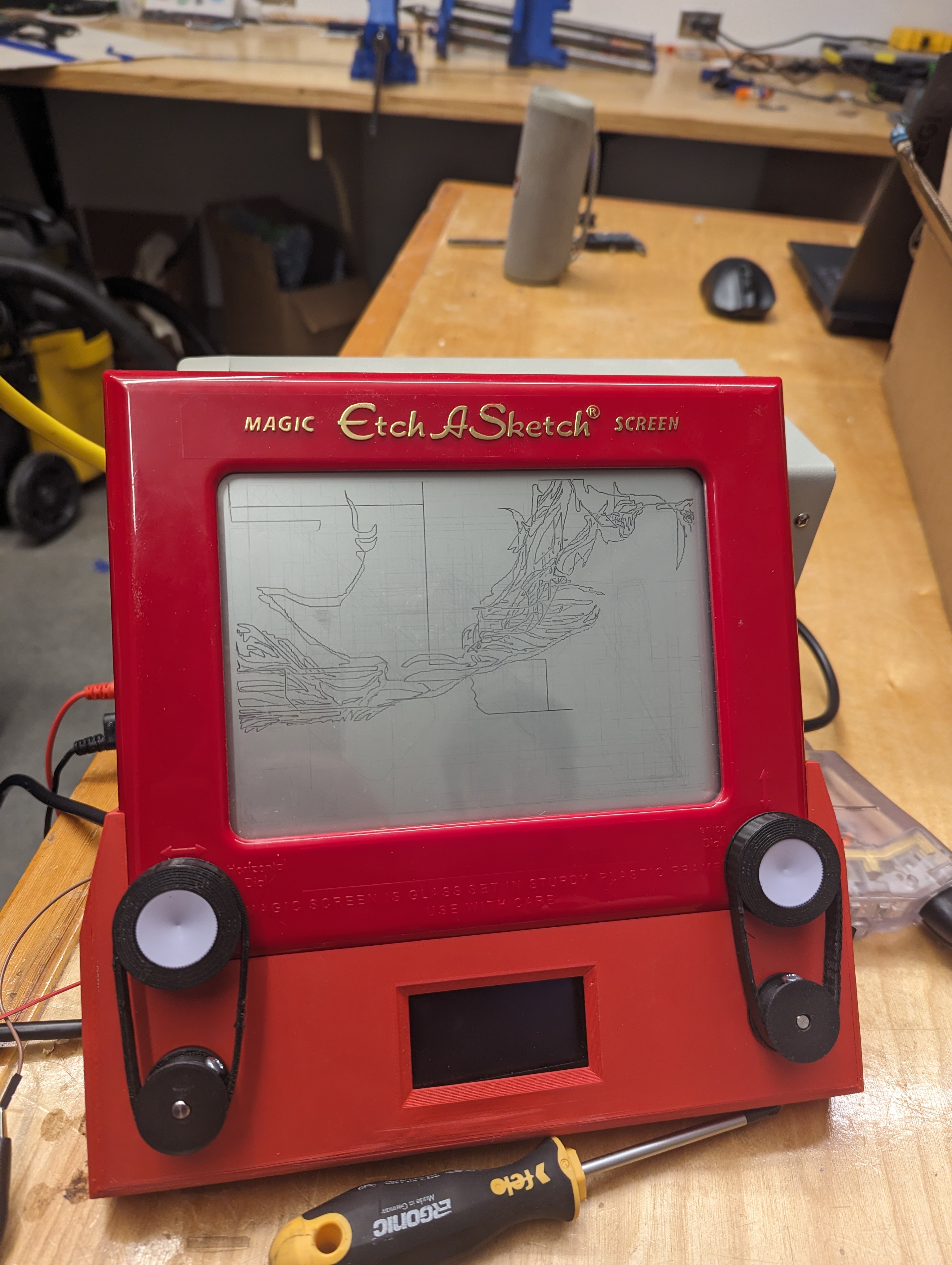
Yikes! Not great, looks upside down, and with no backtracking. JD and I had been working in different repos, so we updated the code to be on the newest version of the algorithm and ran it again.
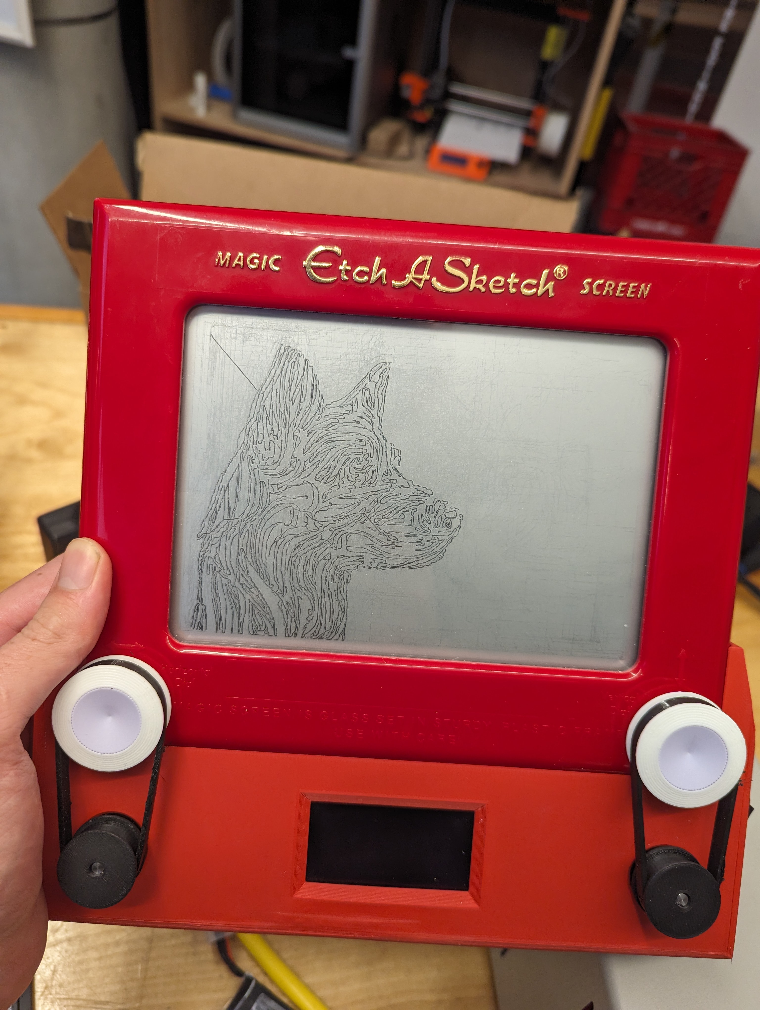
At last it works! We were due to show it off the next day at the De Florex competition, so we swapped out the battery supply for a 9V adapter, and tested the full pipeline.
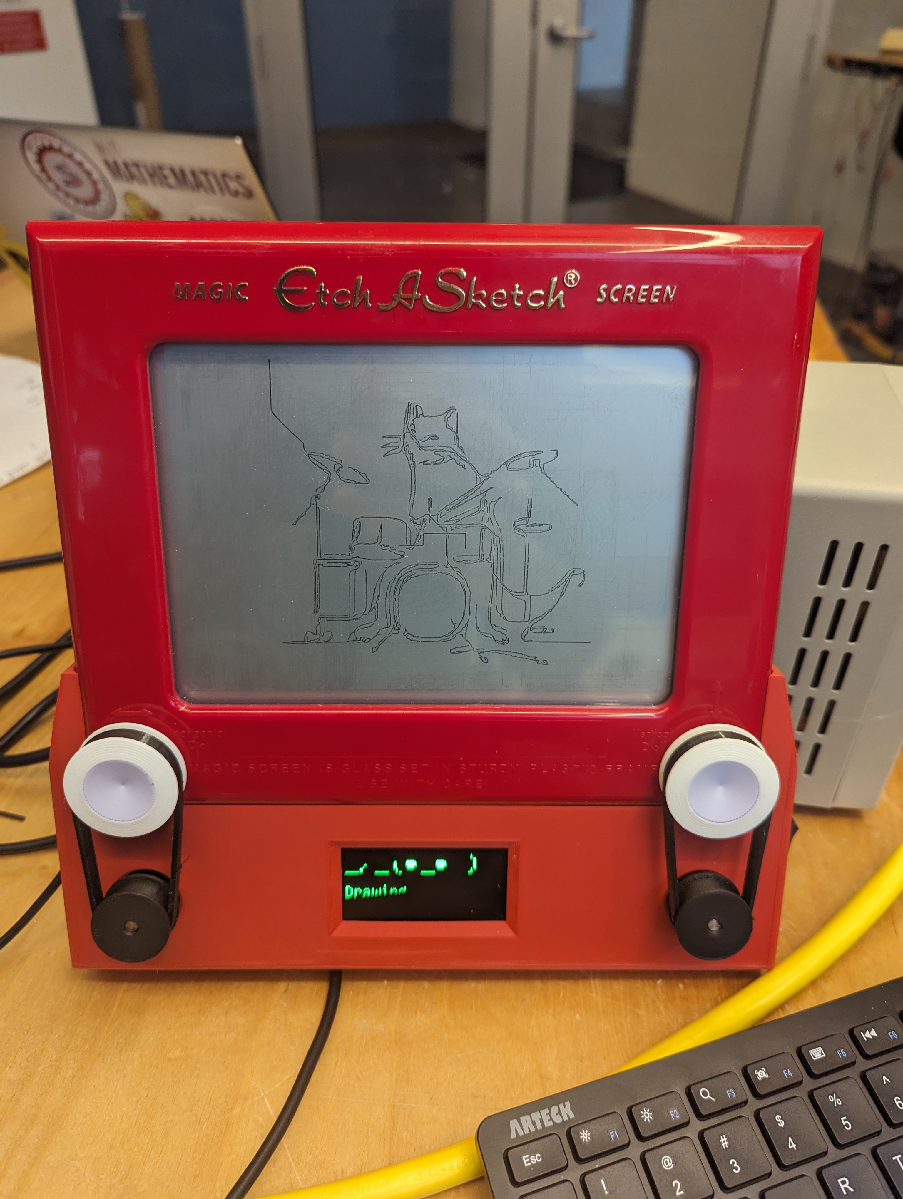
Prompt: "A cat playing the drums"
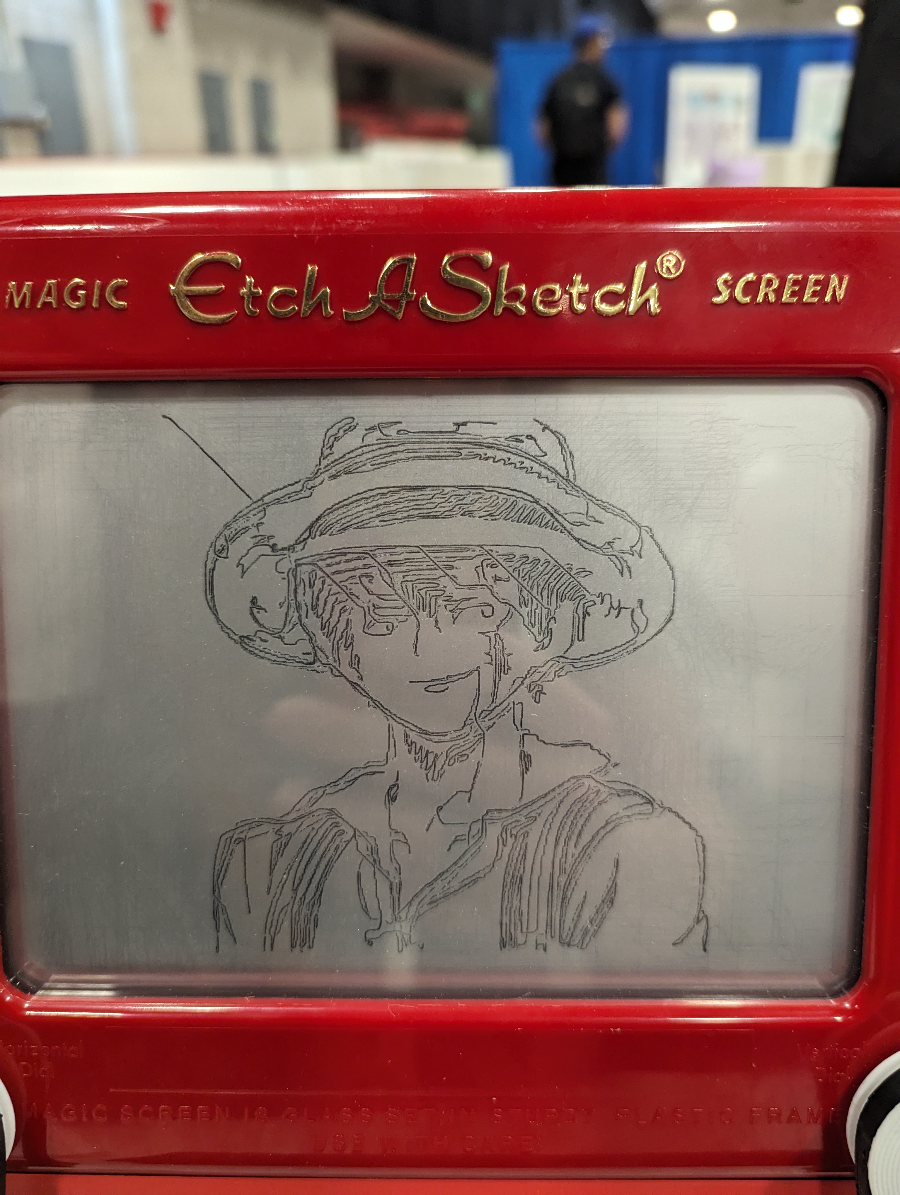
Prompt: "Luffy from One Piece"