2.007 Robot
05/16/2023
2.007!! A classic MIT class normally taken sophomore spring. I was torn between taking this class and the NEET Autonomous Machines version, 2.S007. Eventually I swapped from 2S.007 into 2.007 three weeks into the semester, and then had to build my entire robot three weeks quicker than usual. I think it turned out really cool, but as with everything there's stuff to improve. We were required to keep a design notebook for the class, and many of the notes shown in this recap are taken right out of my notebook. So, here's the journey
Give a look through my entire notebook scanned as a PDF: Notebook
Let me set the scene. 2.007 is a competition robot class, and is actually the class that gave birth to First Robotics (which I did for four years in high school). Every year, the instructors create a new game board, and the students are tasked with individually creating a robot which can solve various tasks on the game board. Each year normally has a theme, with ours being Black Panther themed, as the second Black Panther movie had just been released that year, and it had some scenes shot on MIT campus. Here's the gameboard:
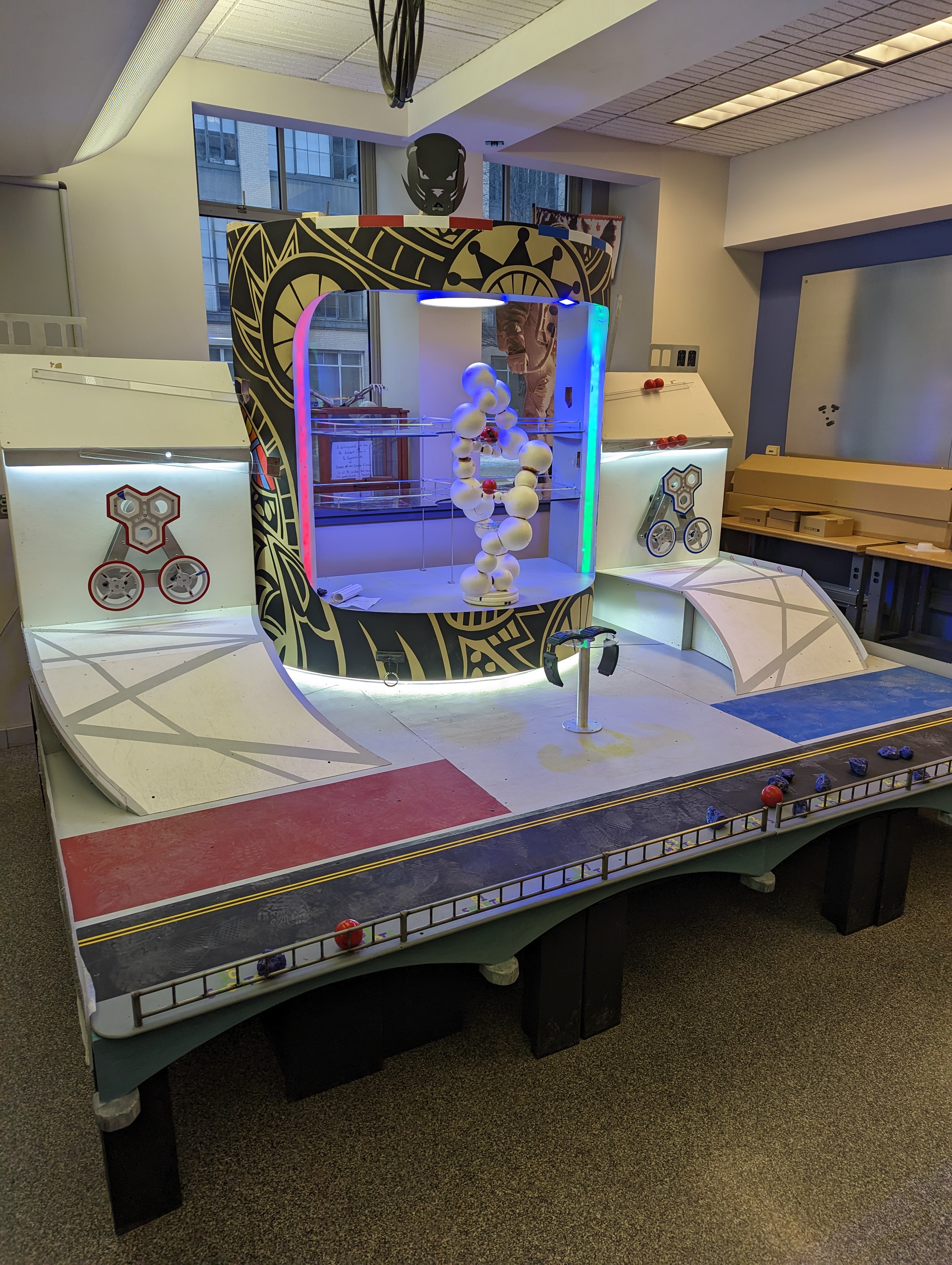
Objectives
There are several objectives the robot can complete for points. After time is up, the robot with the most points wins. I'll go over more of the rules and constraints later on. Here are the objectives in no particular order. I've also linked the full Contest Rules.
2.007 Contest Rules Spring 2023Bracelet:
First player to bring the bracelet to their side of the arena gets 11 points
Lab Centrifuge Spinners
| Speed (RPM) | Outer Pts | Inner Pts | Combined |
|---|---|---|---|
| 25-50 | 5 pts | 3 pts | 8 pts |
| 51-100 | 10 pts | 7 pts | 17 pts |
| 101-150 | 20 pts | 15 pts | 35 pts |
| 151-200 | 40 pts | 21 pts | 61 pts |
| 201-250 | 47 pts | 26 pts | 73 pts |
| 251+ | 0 pts | 0 pts | 0 pts |
In addition, when a centrifuge is held within a particular speed zone for 5 continuous seconds, a ball is released down a chute where it can land on either the upper shelf, lower shelf, or fall all the way to the base of the lab. These positions have 5pts, 2pts, and 0pts , associated with them respectively. There are a total of 5 possible balls to be released.
DNA Helix
| Lower Shelf | Middle Shelf | Upper Shelf | |
|---|---|---|---|
| Single Ball | 21 pts | 27 pts | 48 pts |
| Max (3 balls) | 63 pts | 81 pts | 144 pts |
Vibranium Rocks
The player can earn points by moving the Vibranium rocks to certain locations. By putting the rocks "in hiding", behind the ramp, they can earn 0.5pts/rock. If they place it over the metal fence into "the Charles", they get 3pts/rock. There are a total of 5 pieces of Vibranium per player.
Mask Ring Puller
By pulling on the ring attached to the mask with a resistive spring load, the player can earn a point multiplier. The point multipliers are 1.2x, 1.5x, 1.8x, and 2.0x. The point multipliers also double autonomous period points.
Benzene Ring Torque
Points are awarded by cranking the benzene ring to lift the crucible to Tim to give special beaver powers. Points are awarded for each zone the crucible passed through, i.e. they are cumulative as you move through zones.
| Points | Cumulative Points | |
|---|---|---|
| First Zone | 15 pts | 15 pts |
| Seccond Zone | 11 pts | 26 pts |
| Third Zone | 8 pts | 34 pts |
| Fourth Zone | 5 pts | 39 pts |
Design Constraints and Freedoms
We were limited to what was provided in the Pappalardo Lab and in our kit of tools they gave us. This in combination with the following requirements defined the full set of constraints:
- Autonomous Time: 30 seconds
- Manual Drive Time: 90 seconds
- Space: Has to fit in a 12”x12”x16”box.
- Motors: 4 geared LDO motors plus 4 servo motors
- Materials: 5052 Aluminium bar stock, 1/16th steel sheet stock, delrin stock, bolts and nuts. No more than 6in^3 of 3D printed parts.
- Maximum Stored energy: 50kJ
- Electronics: Arduino, radio, receiver, lipo battery. Maximum voltage of 7.4V.
Mini Me Robot
One of the first assignments we had to complete was to create a small robot “mini-me” which was the barebones minimum project to get any points at all. This little guy could push some of the Vibranium rocks around to score a couple points and nothing more. To create the pusher ramp, I first modeled it in cardboard before creating the real deal out of bent sheet steel.

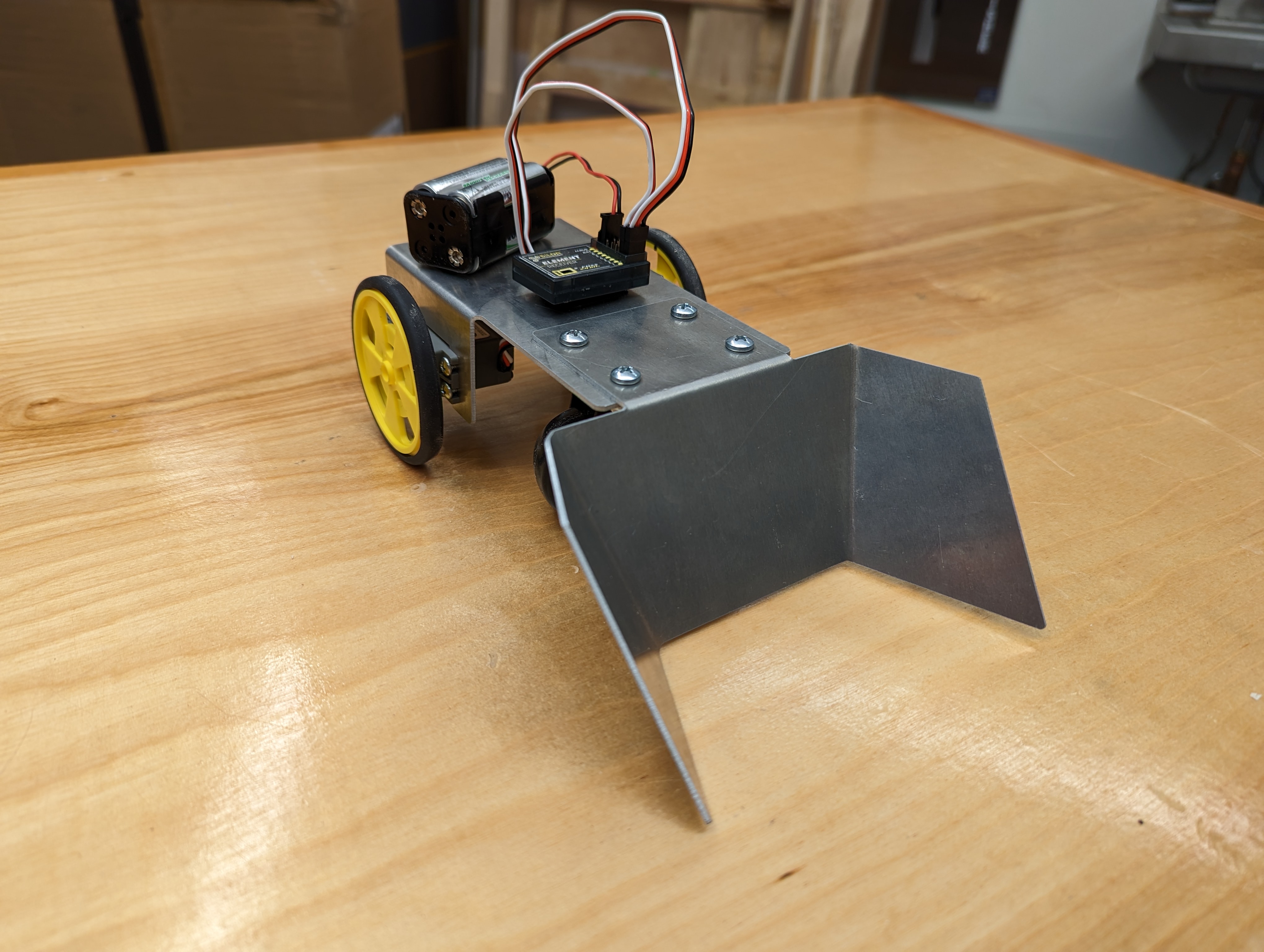
Then for testing to see if it works (with some awful one-handed piloting), first to see if it can push the rocks around successfully, and secondly to see if it could get up the ramp. The brain eating “clean up song" is playing in the background of the ramp song, so please feel free to mute.
Stage Characterization
In order to properly spec my robot, I needed to know the key metrics of the board. This will inform how I size and design components. All important physical measurements were taken, but some more complex characterizations were also done:
Centrifuge Characterization:
For the future specing and design of the spinner, I needed to know how hard it is to get these centrifuges up to speed. There are two components to the resistance, frictional torque and inertia. To measure the frictional torque, I decided to use a spring scale to pull the centrifuge until it moves. While yes, this is measuring static friction and not kinetic friction, which is what would truely matter during operation, static friction values are always larger than kinetic friction. So, the values that I would use would make me over-spec not under-spec my design. The inertia of the wheels was dominated by large steel plates mounted to the shafts on the backside, so to measure the inertia I simply measured the dimensions of these plates and then used the mass of steel and the moment of inertia of a cylinder The measured values were:
| Inner Centrifuge | Outer Centrifuge | |
|---|---|---|
| Static Friction Torque | 0.028 kgm | 0.007 kgm |
| Moment of Inertia (I) | 0.0571 | 0.0133 |
| Radius | 0.1016 m | 0.1016 m |
Coefficient of Friction
To know how much traction my robot would be able to get, I needed to know the coefficient of friction between the rubber on the wheels provided and the floor of the game board. This was measured by making a little test piece of aluminum with 4 wheels screwed onto it and pulling it with a spring scale. This could then be used to calculate where the center of mass must be to ensure a No Slip No Tip condition.
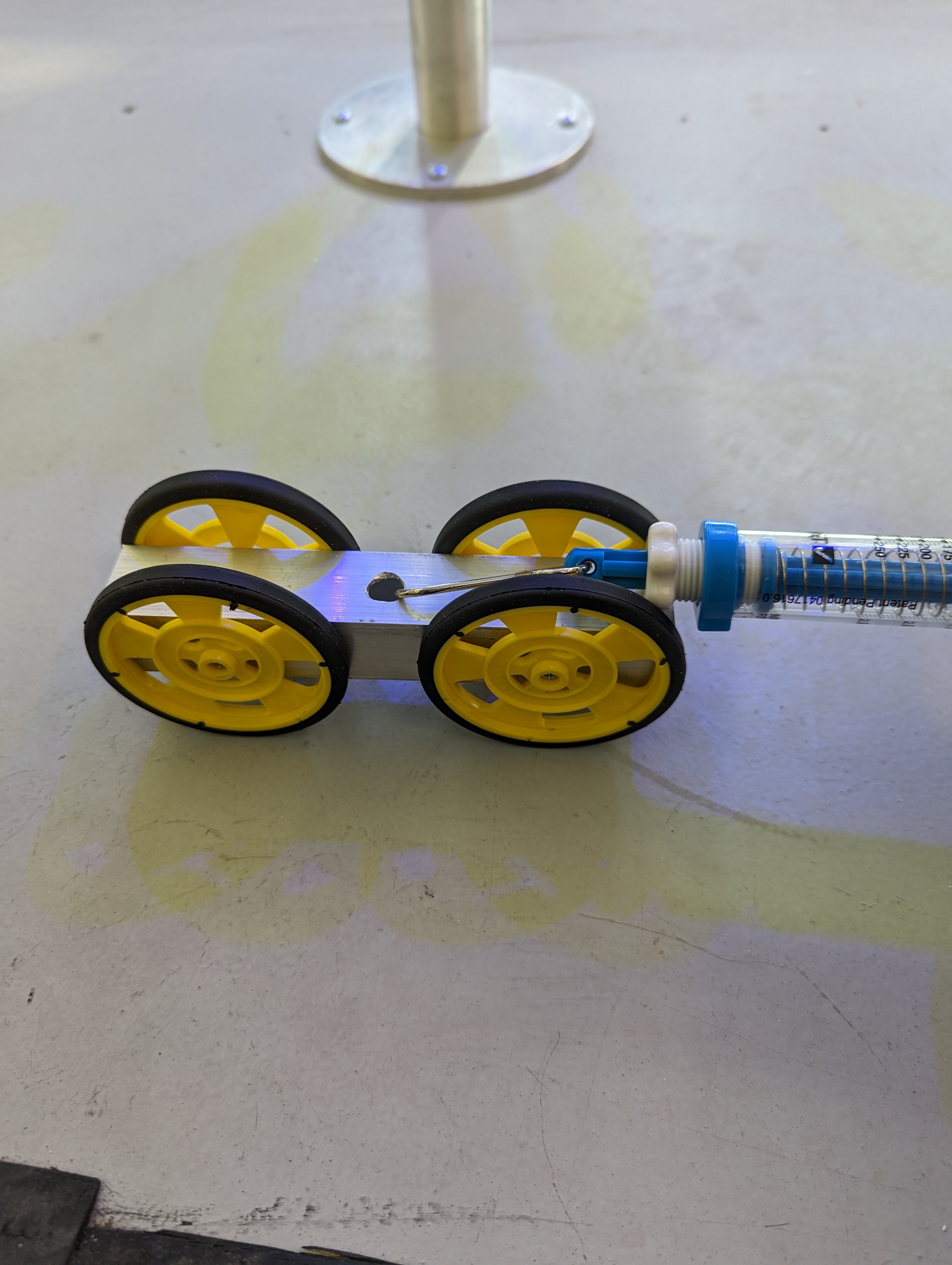
Here's the No Slip No Tip derivation: No Slip No Tip Derivation
Strategy
The first step to solving the actual problem of completing the tasks was to develop a strategy. In this context all a strategy just means a list of tasks to achieve, and rough timings to do it in. This should not contain anything more than a suggestion how it would actually be designed. I'm just going to copy straight out of my notebook here and show the strategies I came up with. From a first pass over, and actually standing next to the game board, it seemed like going for the DNA was a waste of time. It would be technically difficult to achieve, and didn't give that many more points. I came up with five rough strategies that I could pursue.
Here's page 11 of my notebook, which has the original sketches and strategy mockups: Strategies in page 11 of notebook
Strategies that I thought worth thinking more about had a schedule built out, where I could see if it was possible to even do the things I wanted in the time provided.
Example schedule
| Autonomous Start | 0s - 30s | |
|---|---|---|
| 0s - 5s | Deploy and activate detachable mask ring puller | |
| 6s-14s | Get to centrifuge and position spinner | |
| 14s-30s | Get centrifuge to 225 RPM | |
| Autonomous End | 30s - 120s | |
| 31s - 55s | Maintain 225 RPM on both Spinners | |
| 56s - 120s | Grab bracelet if free or push Vibranium to my side |
Wanting to push myself in the class and also make the most capable robot possible, I decided to go with the tryhard strategy:
- Autonomously do both centrifuges to 200-250
- Place 3 balls in DNA upper shelf
- Ring pull to 2.0x
Initial Design
The general system design in my head at this point looks something like the following:
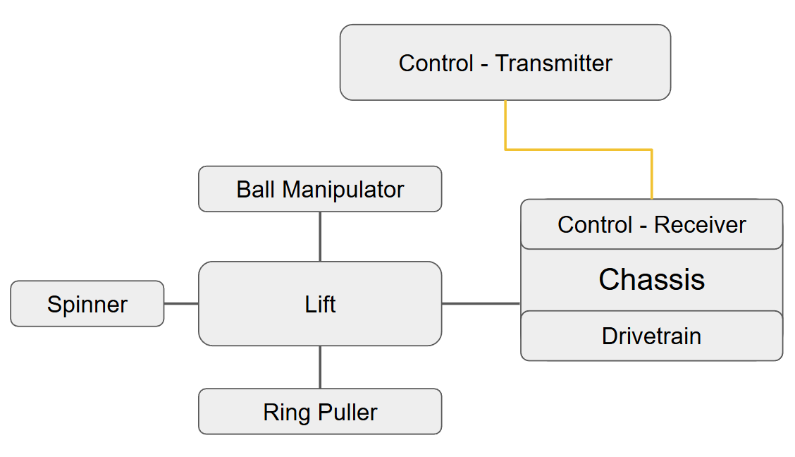
The question is what are my implementations for each of those subsystem blocks going to be? On pages 18-22 in my notebook I went through a bunch of possible designs for each subsystem and select solutions out of the options I came up with. The ending implementation selections are:
| Subsystem | Purpose | Selected Design |
|---|---|---|
| Drive Train | Move and orient the robot around the board and up the ramp | Tank Drive |
| Centrifuge Spinner | Spin both centrifuges to 200-250 RPM | Center Wheel Spinner |
| Ring Puller | Grab onto the ring and railing and pull the ring mask multiplier | Pivoting Simple Hook and Winch |
| Ball Manipulator | Pick up, store, and dispense balls into the DNA Helix | Conveyor |
| Lift | Move the Centrifuge Spinner and Ball Manipulator into their respective positions as needed | Double Reverse Four Bar |
Calculations
While I could just go "eh, that's about the right size" for most things I make, the motor restrictions on this project made me actually need to optimize what motors went where, and how I could expect them to perform.
Centrifuge Motor Selection
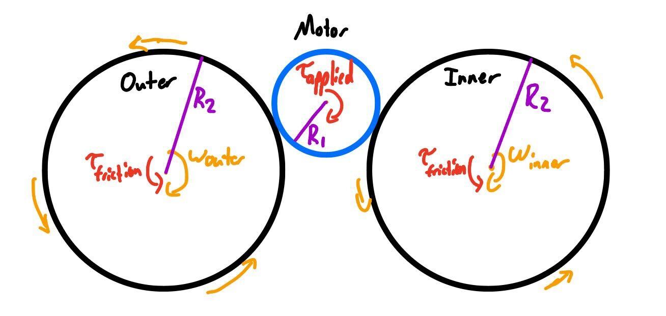
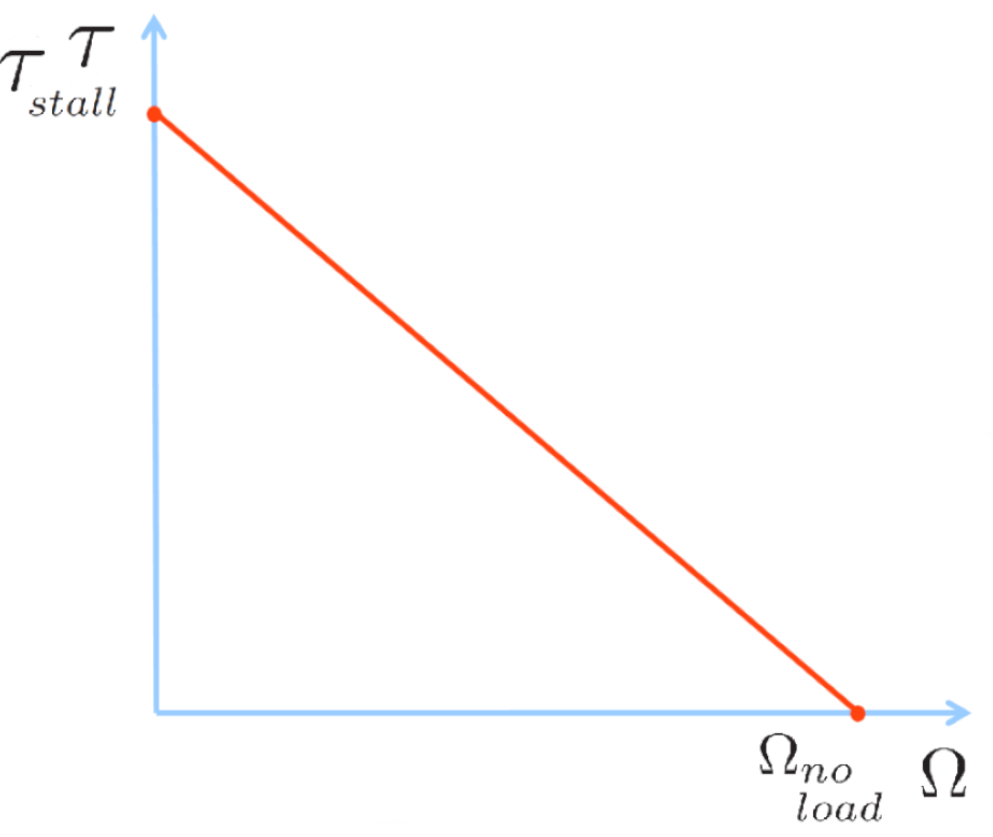
Given the limited time in a competition round, I needed to identify possible slow downs. One that I was worried about was the speed to get the centrifuges up to speed. Given a certain driving motor how long does it take for both centrifuges to hit 200 RPM? The complication with this is that a motor's torque is a function of its speed, this forms a differential equation that I needed to solve. A typical DC motor speed curve is shown below, this is where the equation comes from. The stall torque is the torque at 0 RPM, and the no load speed is the speed at which the motor is not under any load.
Then we just solve the differential equation, using Variation of Parameters (or Wolfram Alpha, it's 2023), and initial conditions:
Now if we plug that information into Desmos along with the characteristics of the centrifuge and the LDO motor, we can see how long it takes to reach 200 RPM.
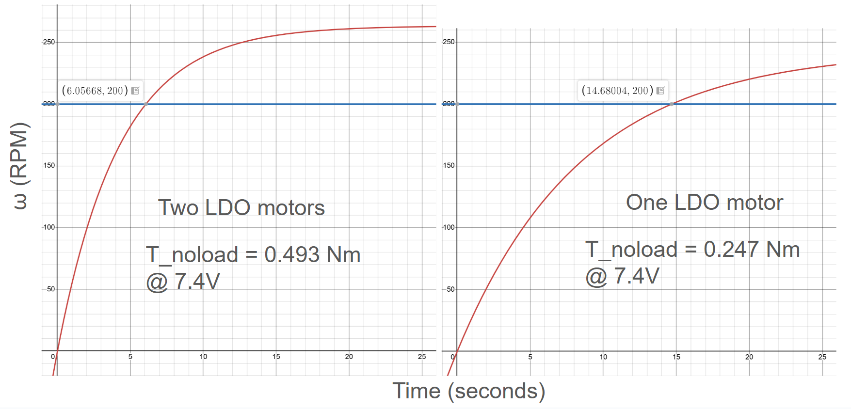
Clearly one vs two motors makes a big difference, taking 6 seconds with two motors and over 14 seconds with only one. But if I do a central spinner like in the drawing at the beginning of this section, then the speed of the motor will be dropped down by That means that I'd just have to use a lower geared LDO motor, they all have the same power.
Winch Sizing Calculation
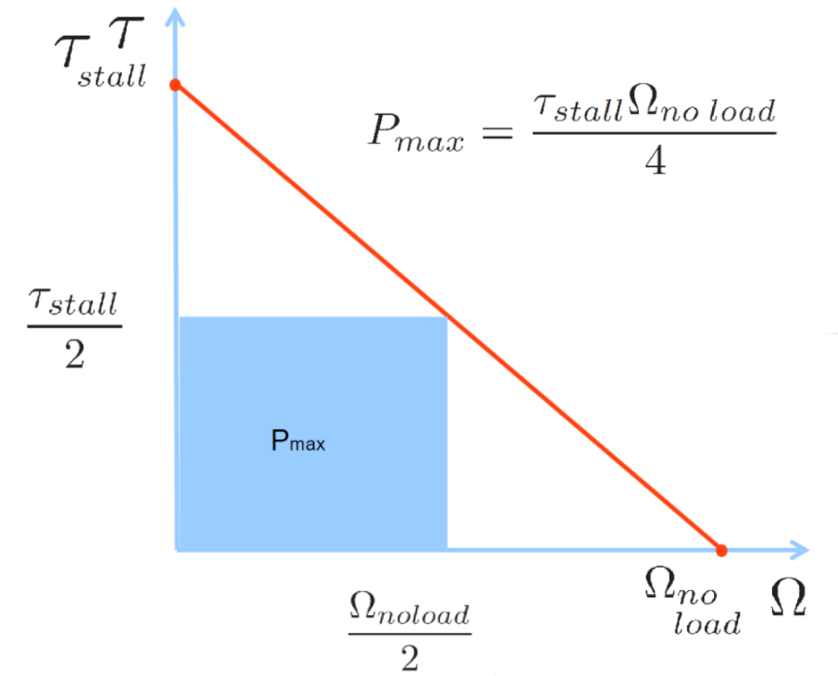
The goal of the winch is to be able to pull in the 60N of force the ring puller requires as quickly as possible. The question is how do I size my winch to do this given a specific set of motors to work with? As we have already seen with the Centrifuge spinners, the torque speed curve tells us that different torques are related with different speed. In this case though it helps to think of power, . If you look at the graph below you can see that max power is at half the no load speed and half the stall torque. If we want to pull in the ring as quickly as possible, we want to target for maximum power. “How do you know you shouldn't just aim for a higher speed?” The issue with that is that that higher speed would require less torque on the motor, which means a smaller diameter winch, which means less rope pulled in for every rotation. If you do out the derivation of using the torque equation with the radius of the winch to maximize the speed of the pulled in rope, you do actually arrive at the same answer as “use aim for max power”. I would put it in here but I don't want to clean and format the math, just do it yourself lol. With the goal of max power in mind, here is how I sized the winch to decide between an LDO motor and a Torque Servo. First the graph showing max power:
As with all problems a good place to start is with a free body diagram, even if it's super simple.
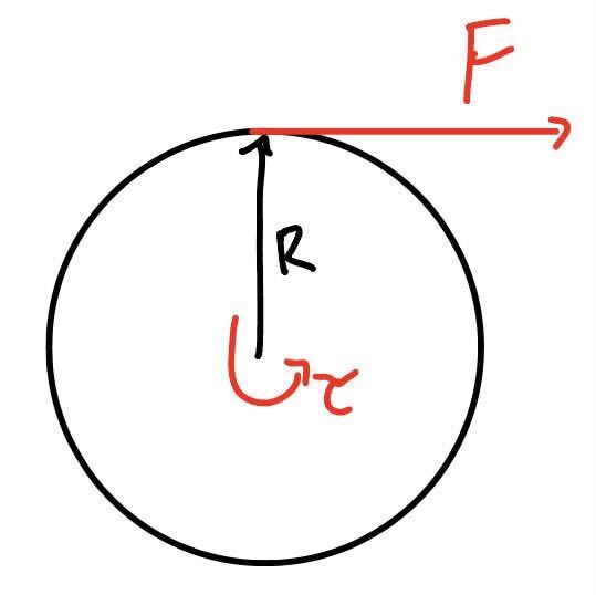
Using these equation and the spec sheets for the LDO and servo motors, we get the following metrics. The Torque Servo has nearly double the power of the LDO, and is thus clearly a crucially option in this case where we are aiming for max power.
| Motor | Stall Torque | No Load Speed | Max Power | Winch Radius | Winch Speed |
|---|---|---|---|---|---|
| Torque Servo (Bilda) @7.4V | 2.47 Nm | 60 RPM | 222.3W | 2.06 cm | 6.48 cm/s |
| LDO Motor (Pololu) 217:1 @7.4V | 2.34 Nm | 34.5 RPM | 121.1W | 1.95 cm | 3.52 cm/s |
Lift Design
The lift was designed using a previous year's robot as inspiration, one built by a Steven Davis. Because of that I knew the design fundamentally would work, it was just my implementation that would differ. Regardless, this whole writeup is happening in November 2024 because I had a SpaceX interview I needed lots of math for, so here's some math I did describing the torque about the lifting arms.
The lift is a double reverse four bar linkage. The highest torque loading case is when it in the case shown below. The lifting system will need to be able to supply slightly greater than that amount of torque to lift this thing up.
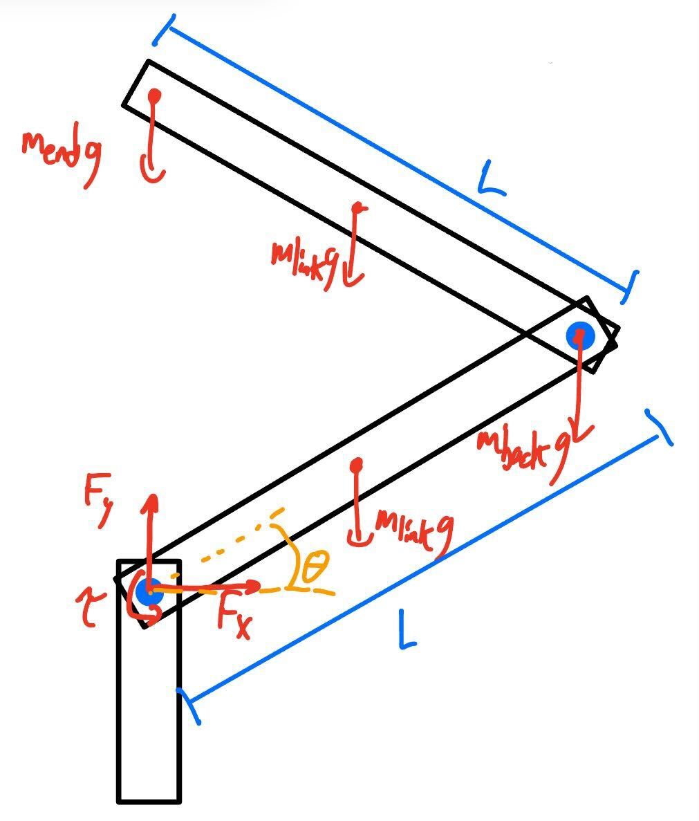
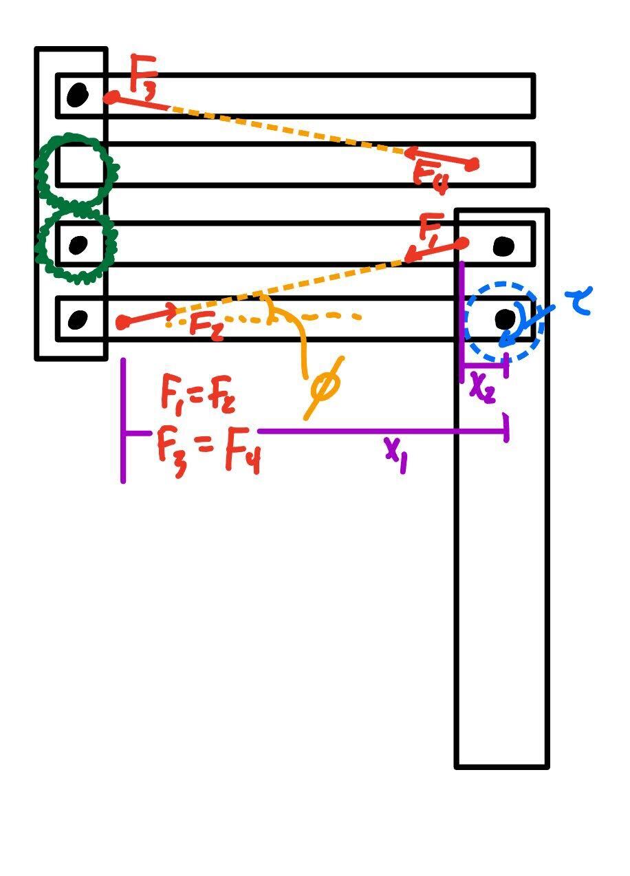
The left image shows the lift without any helping rubber bands. The right image shows the lift in it's maximum-torque-needed state with arrows showing how the rubber bands would act. If you take a torque balance, you begin to see the benefit of using the rubber bands
The idea is that the farther out rubberband location provides a lot more torque since . You can tell that the rubber bands would work quite well by plugging in some numbers the torque balance equation. To test out the maximum torque case, let's set . For , let's take the x = 10in and h = 3in, this results in . For \Tau_{base}, lets take . This results in . Assuming an average rubber band can exert 1 N of force, we should need about 14 of them to fully support the lift. And if you look at the final version of the robot lower down, that's about the correct number. Regardless, it's very reasonable for a bunch of rubber bands to exert 13.5 Nm when attached over the 4 sets of arms.
Ball Manipulator - Most Critical Module
The 2.007 instructors stressed on us the importance of identifying your design's "Most Critical Module" or MCM. This module isn't necessarily the most complicated, but rather the most uncertain. By knocking it out of the way early, you can be more confident that the rest of your design will work as expected. For my robot, my MCM was the ball manipulator to place the balls in to the DNA helix.
In order to maximize point totals, I had the initial idea of my manipulator also picking up balls dropped on the ground. Manipulators like this are common in First Robotics FRC, so my idea echoed many of the designs in FRC, a pivoting front arm with a conveyer bringing balls into a chute. After some CADing I first came up with the following design, and exploded view showing how it would be assembled.
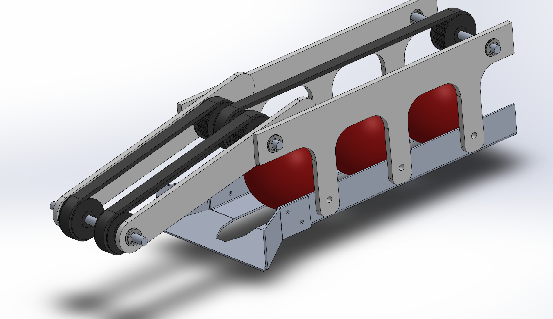
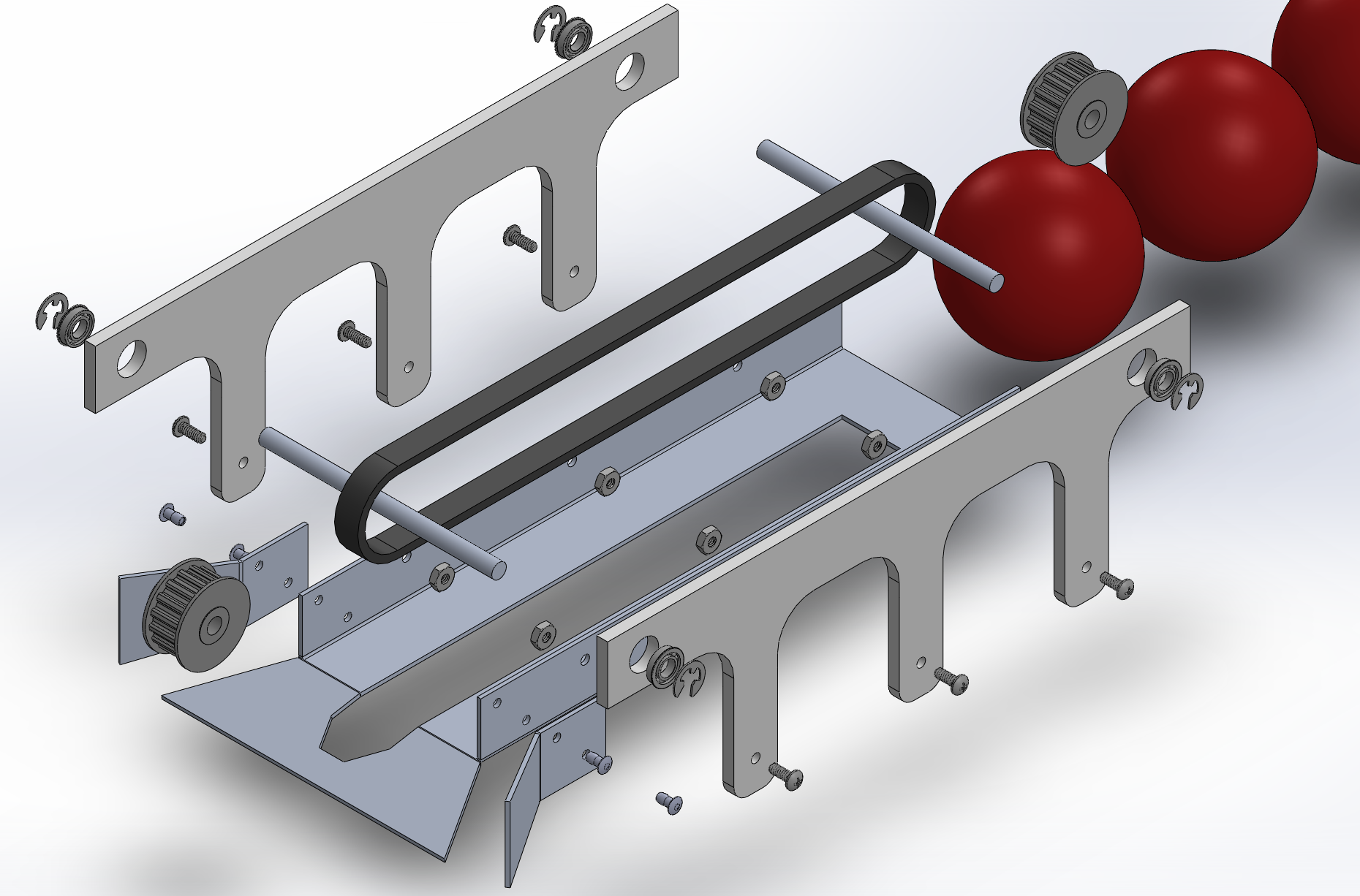
The design uses a series of rotating belts to pull in and control the positions of the game balls. However, I was worried about the balls getting jammed due to a lack of clearance, and asked Sangbae Kim for advice. After a brief conversation, we decided to scrap the whole ball intake function, as time and luck would both limit the usefulness of this feature. Would it work? Probably. Did it need to? No. I could score enough points just fine without picking up the balls on the floor and it's doubtful I would even have the time to do so anyways. So I resorted to the most fundamental design principle:
KISS: Keep It Simple Stupid
So I got rid of the intake mechanism, as now it only needs to move balls in one direction. A simple gate was the first idea that came to mind, with gravity feeding the balls forwards and an arm stopping them from advancing one at a time. Other ideas included putting a belt with tabs underneath the line of balls so that they would neatly advance in a line. This idea was rejected since attaching those tabs to a belt in a secure manner would be difficult and time consuming. After a little bit of CADing the new drawings, the new design was born: a much simplier design which uses a servo motor to control a gate parallel to the flow of the balls. The first version is on the left, with a top mounted gate. After having worries about jamming and the supporting plate bending, I swapped to the design on the right. It uses a cage to contain the balls from escaping, with the section above the gate being compliant to prevent jamming. The spinner was laser cut out of acrylic.
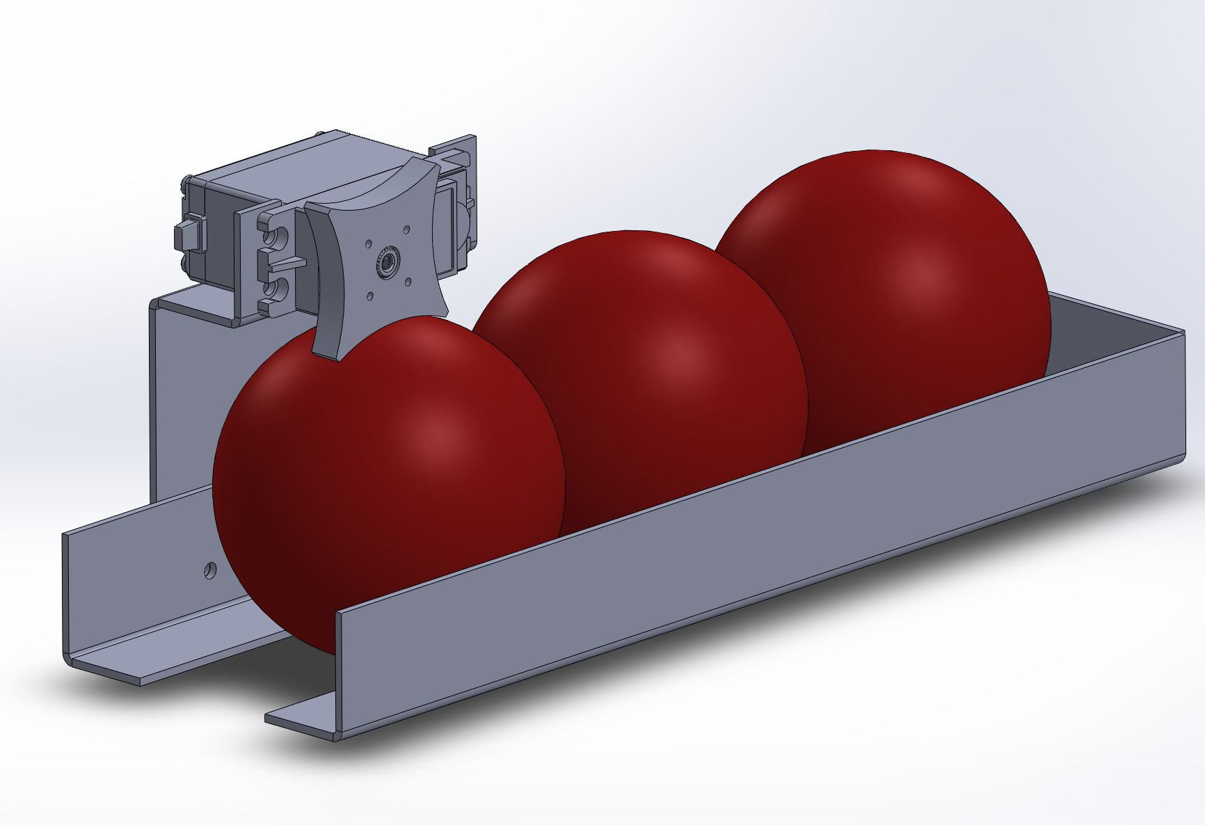
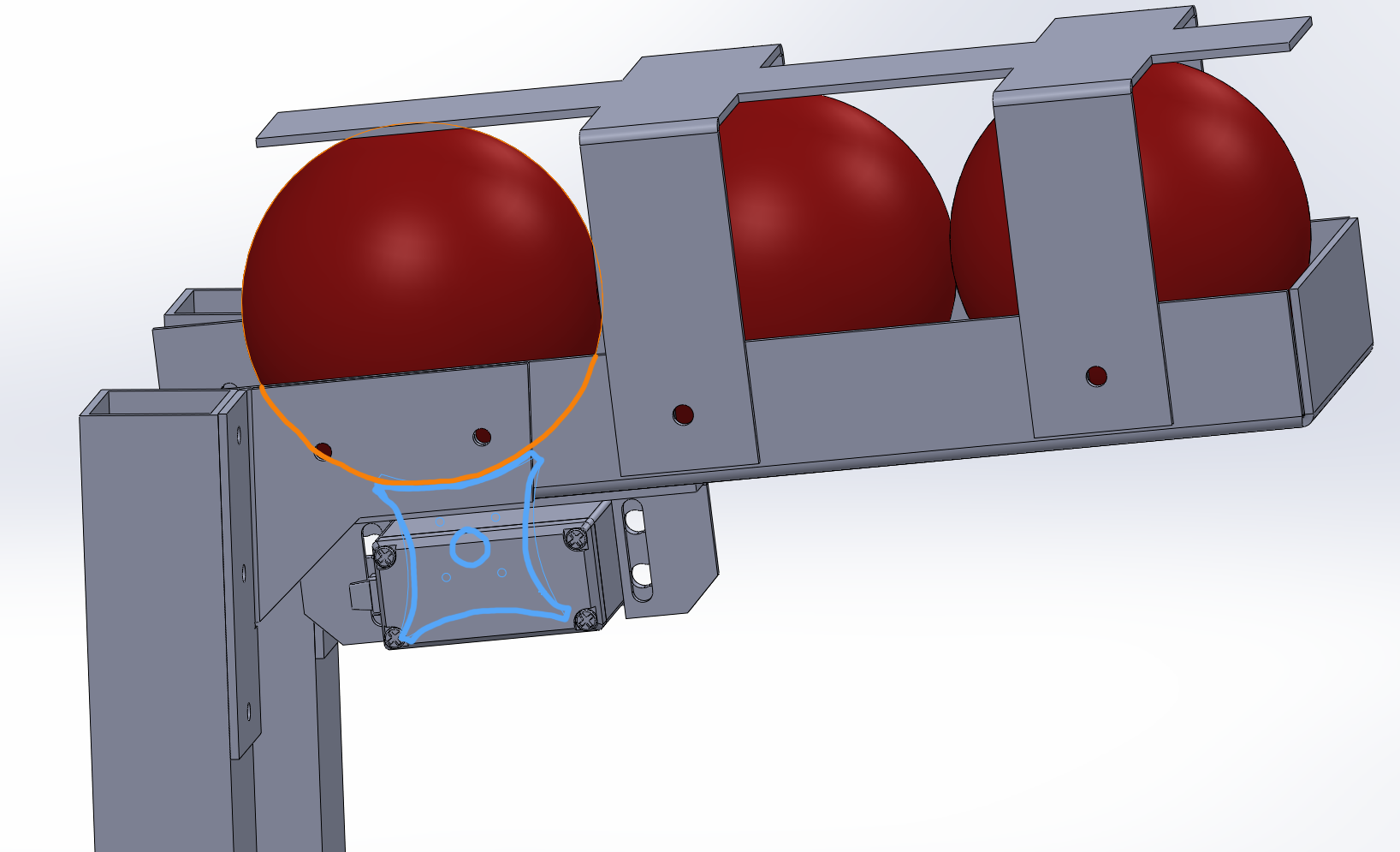
This ultimately resulted in an MCM which was easy to construct and worked reliably on the first try, a pipe dream in the engineering world.
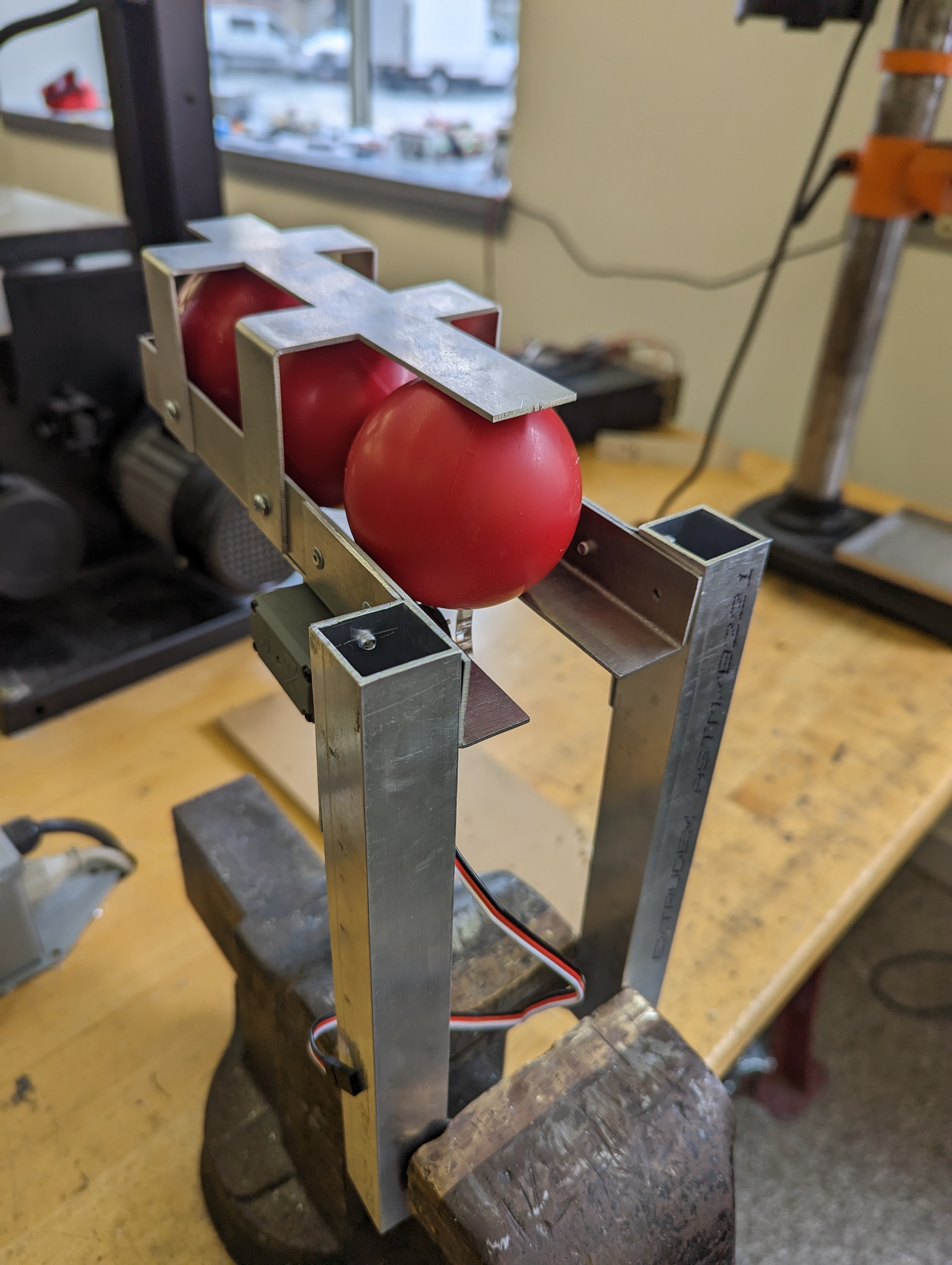
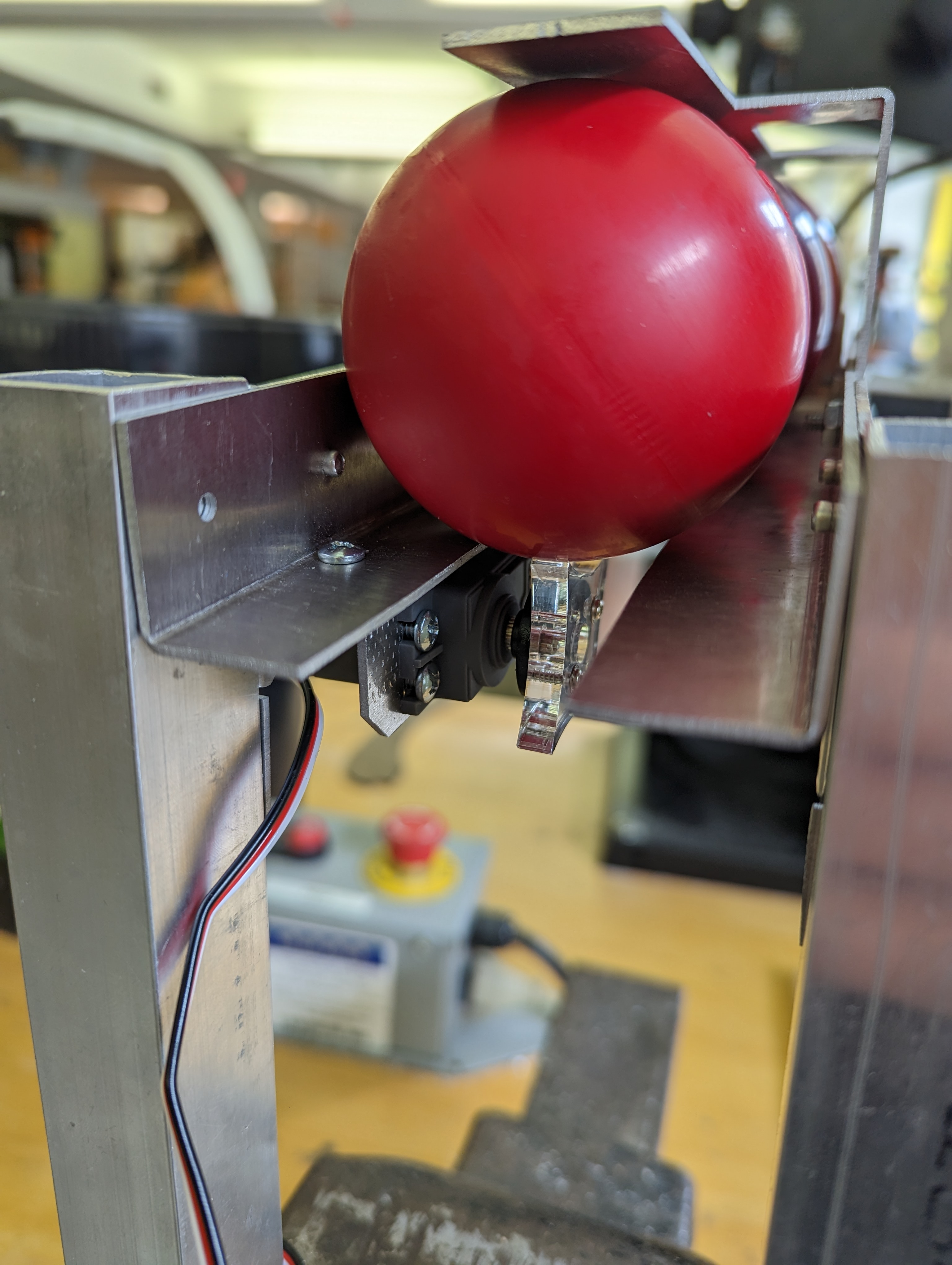
Ta-da! After I showed it to Sangbae, he said he liked the solution and was going to encourage his lab section to adopt the design. :)
Building the Lift
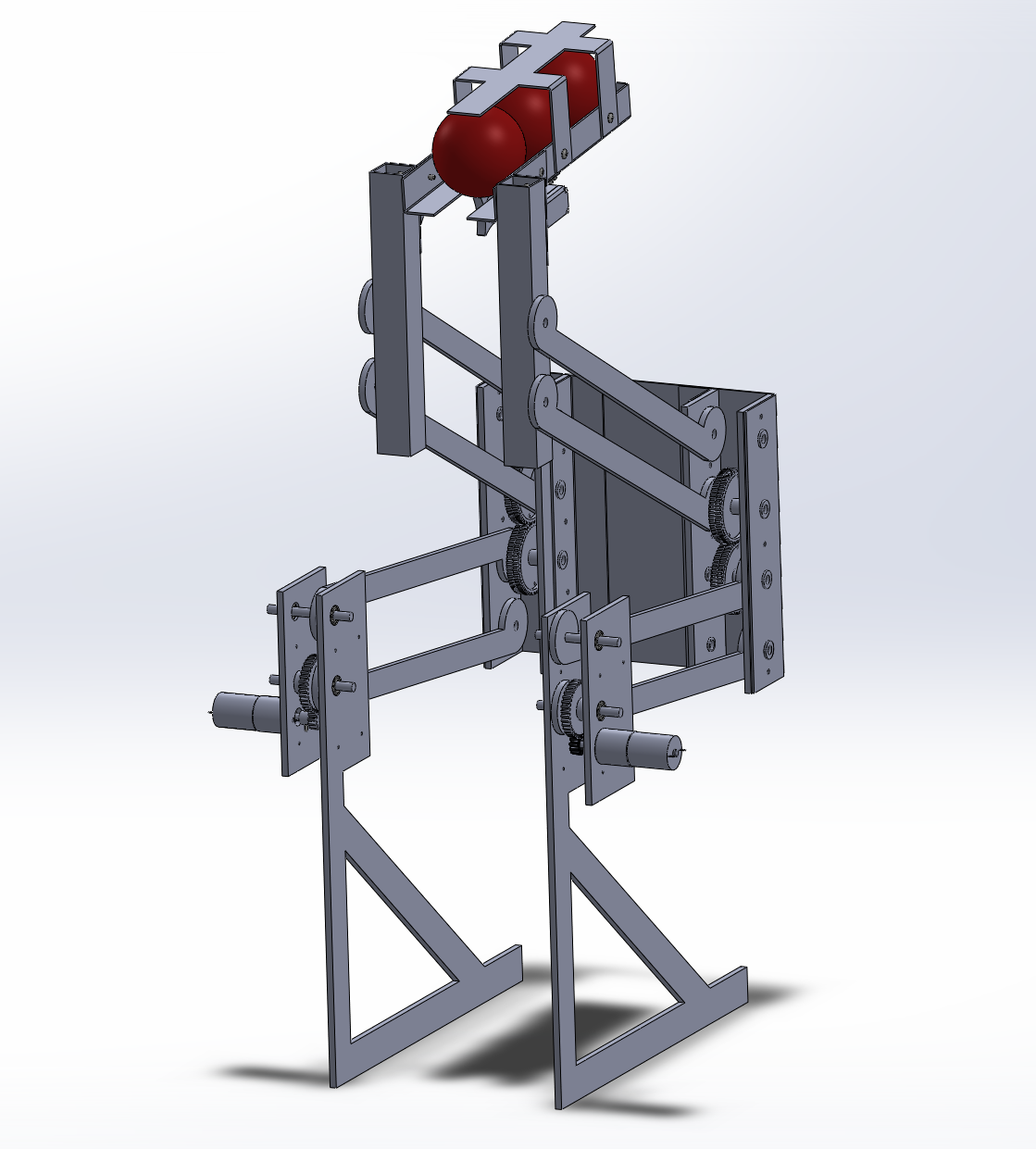
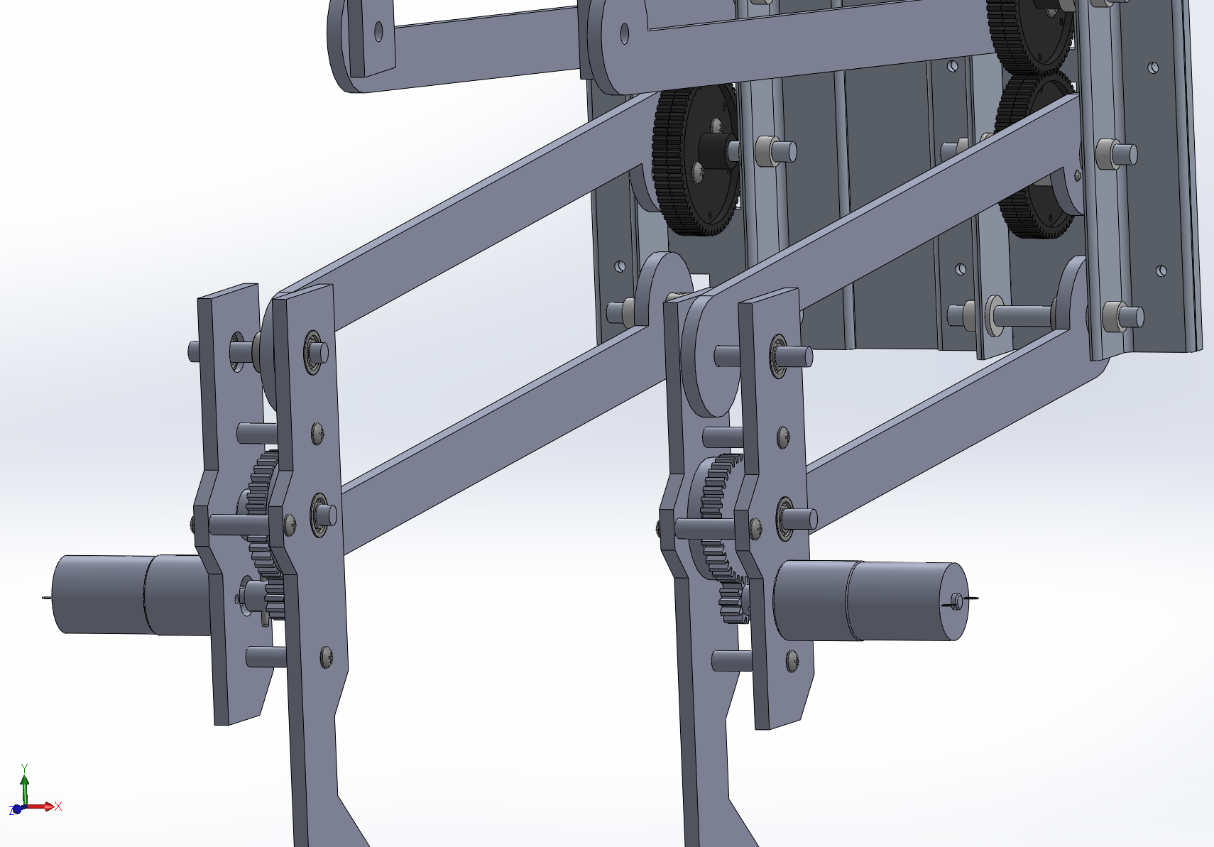
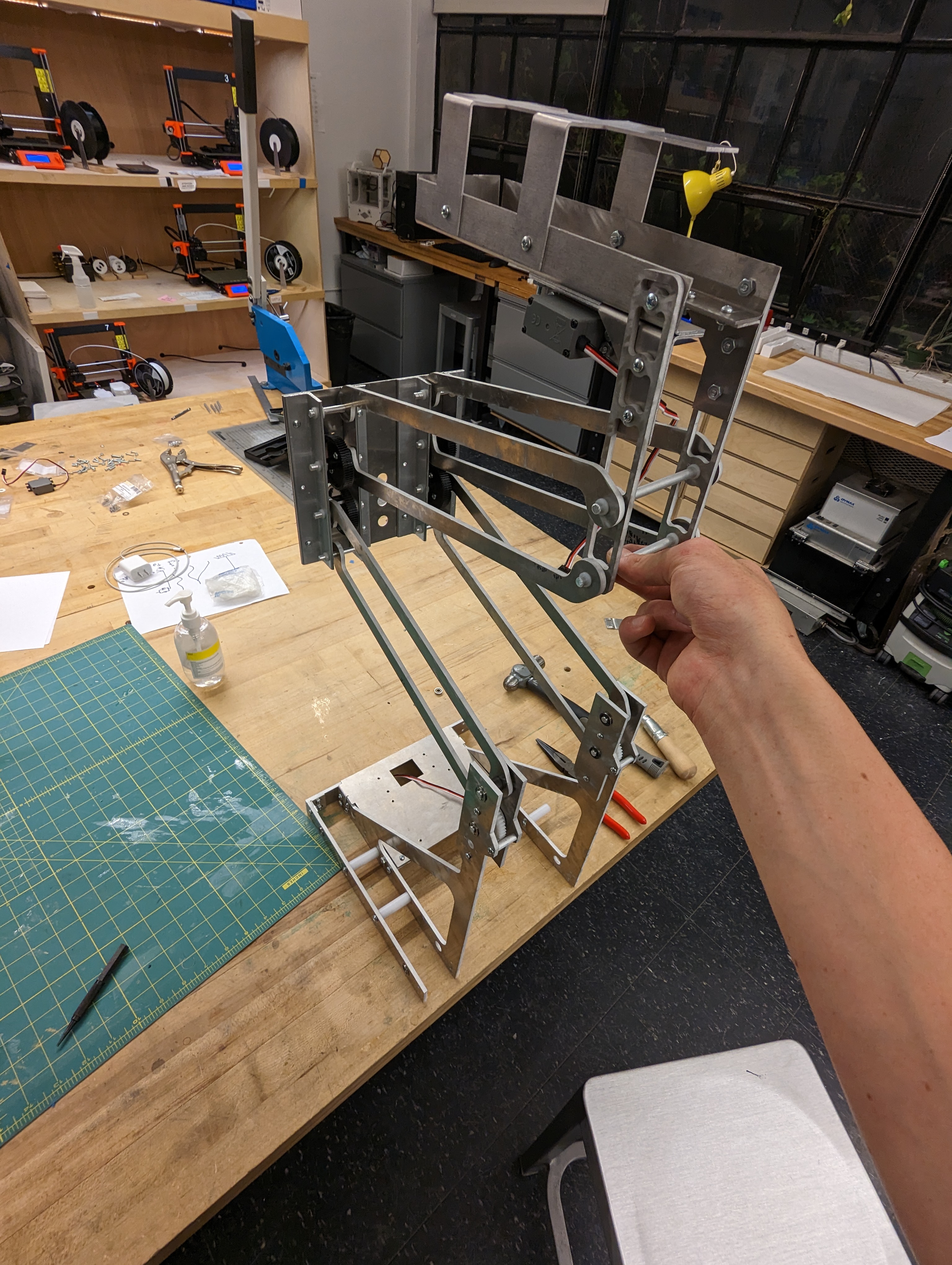
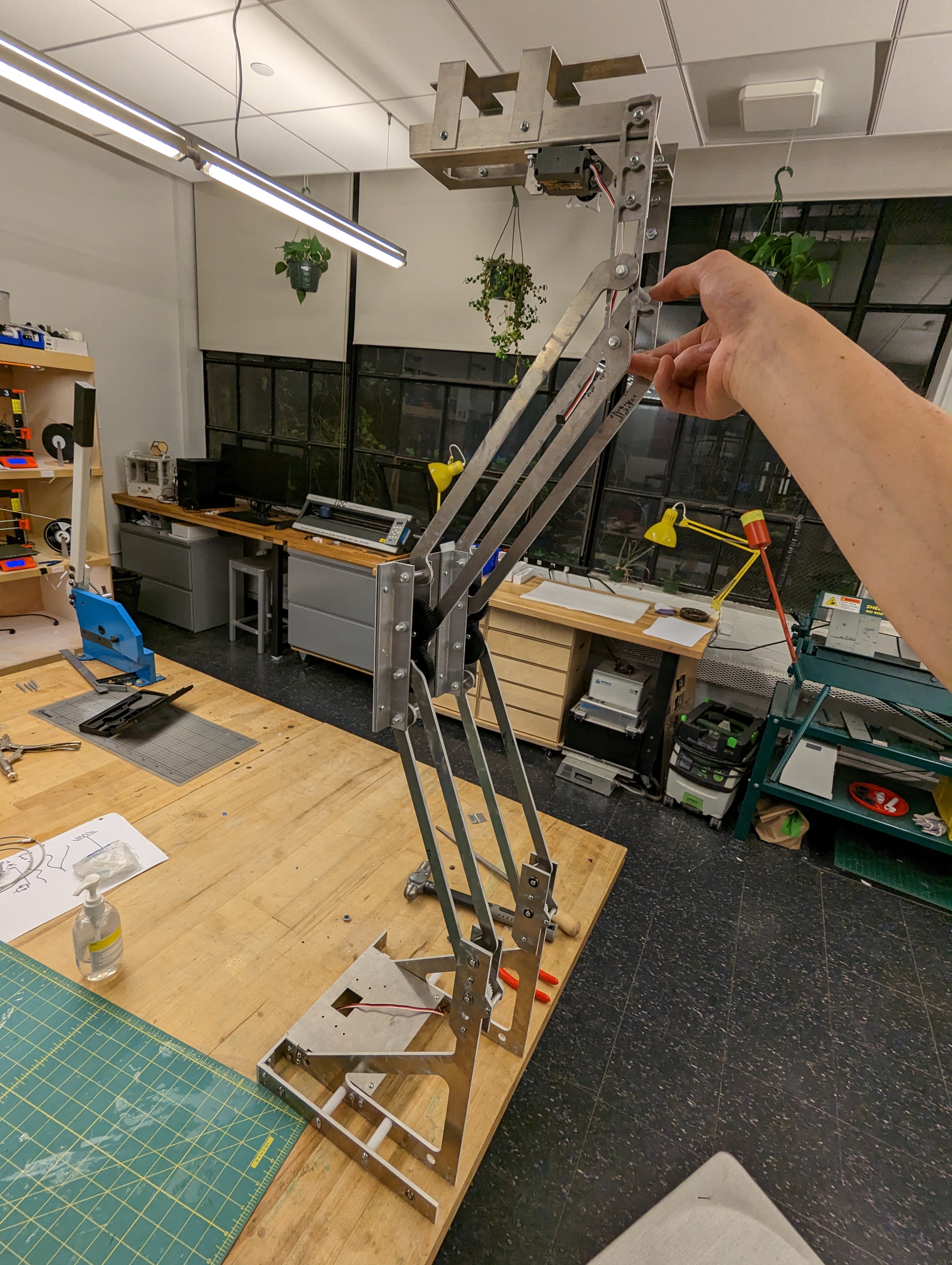
I had only done the MCM at this point, which was very nice to have as a completely reliable component, but there was the entire remainder of the robot left. Thankfully, I started learning how to CAD all the way back in my sophomore year of high school, so I was very comfortable in Solidworks. This would shape up to be my most complex mechanical project with the largest number of parts, so having a solid foundation in CAD was crucial in planning out how parts would interact. The next order of business was the lift, since it was the subsystem I was the least certain how to construct, after the MCM of course. The purpose of the lift is to lift the ball gate and spinner into position so they can place balls into the DNA helix and spin the centrifuges respectively. I decided with a reverse double four bar linkage because I wanted to have a back mounting point for the spinner. This design requires relatively tight tolerances and good construction to work successfully. One of the key things I tried to maintain in my design of the lift was a clean breakdown of parts, so that invariably, when I needed to upgrade or fix a part, I could do so without having to replace the whole structure it is attached to. Also, it is almost 100% water-jet-able, minus only the L brackets on the back which support the axles. This, again, allows me to save many hours manufacturing and upgrading the structure. The following early draft shows the basic shape of the double four bar linkage I was planning on from my initial sketches. There's details missing in the gearing in the back, but it's beginning to take shape. At this stage the lift has no drivetrain or chassis, but that will eventually fit around the base of the triangle supports. Two 217:1 LDO motors drove the linkage, with plastic gears further reducing the gear ratio 3:1. Even with all this reduction, it only took about a half revolution of the motor to lift the motor to the full height. All the gears were plastic which would prove to be an issue with some of the teeth snapping off of the tiny gear pinned to the motor due to too high torque before I mounted the rubber bands.
After pulling an all nighter, I have it made:
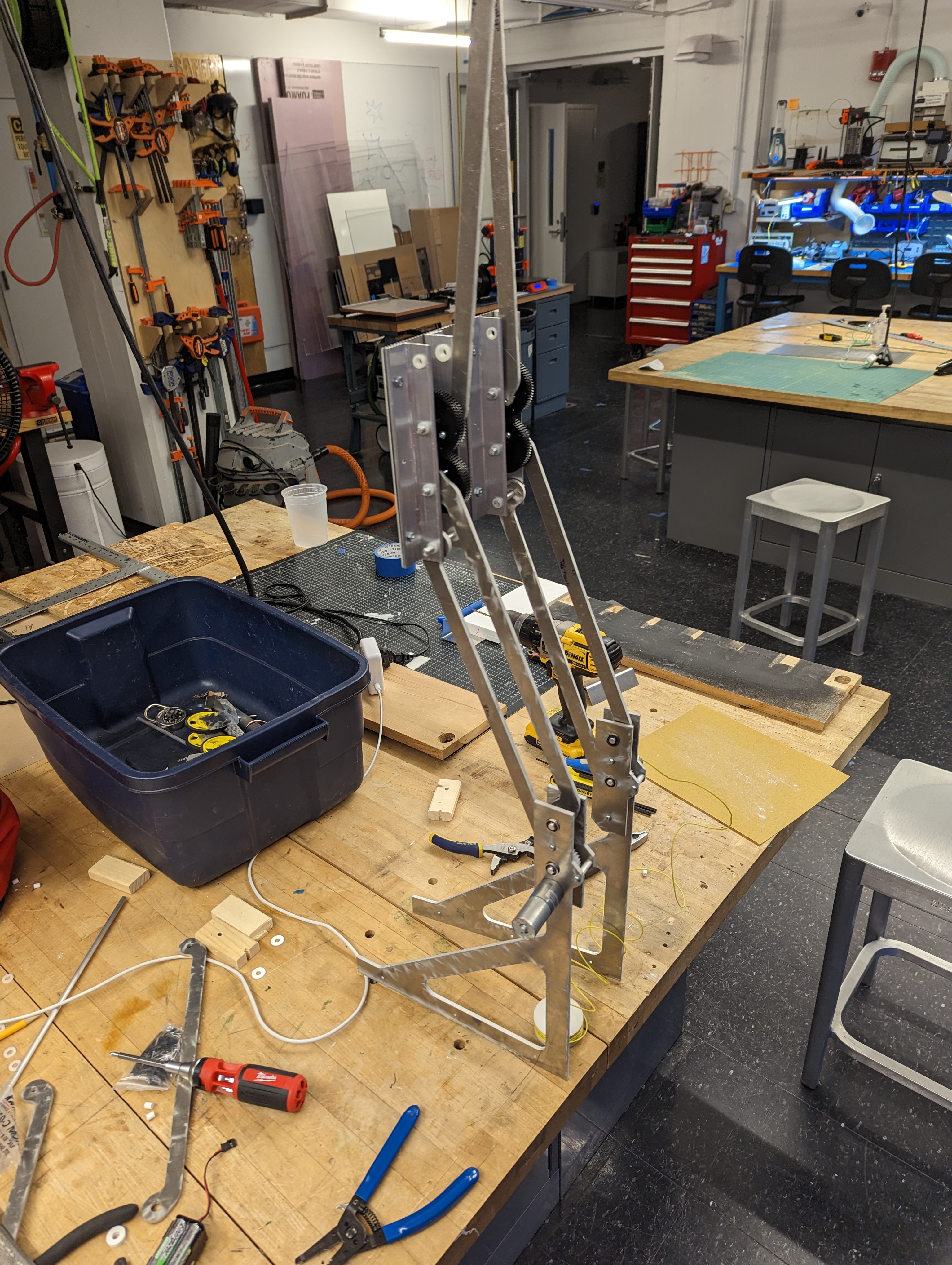
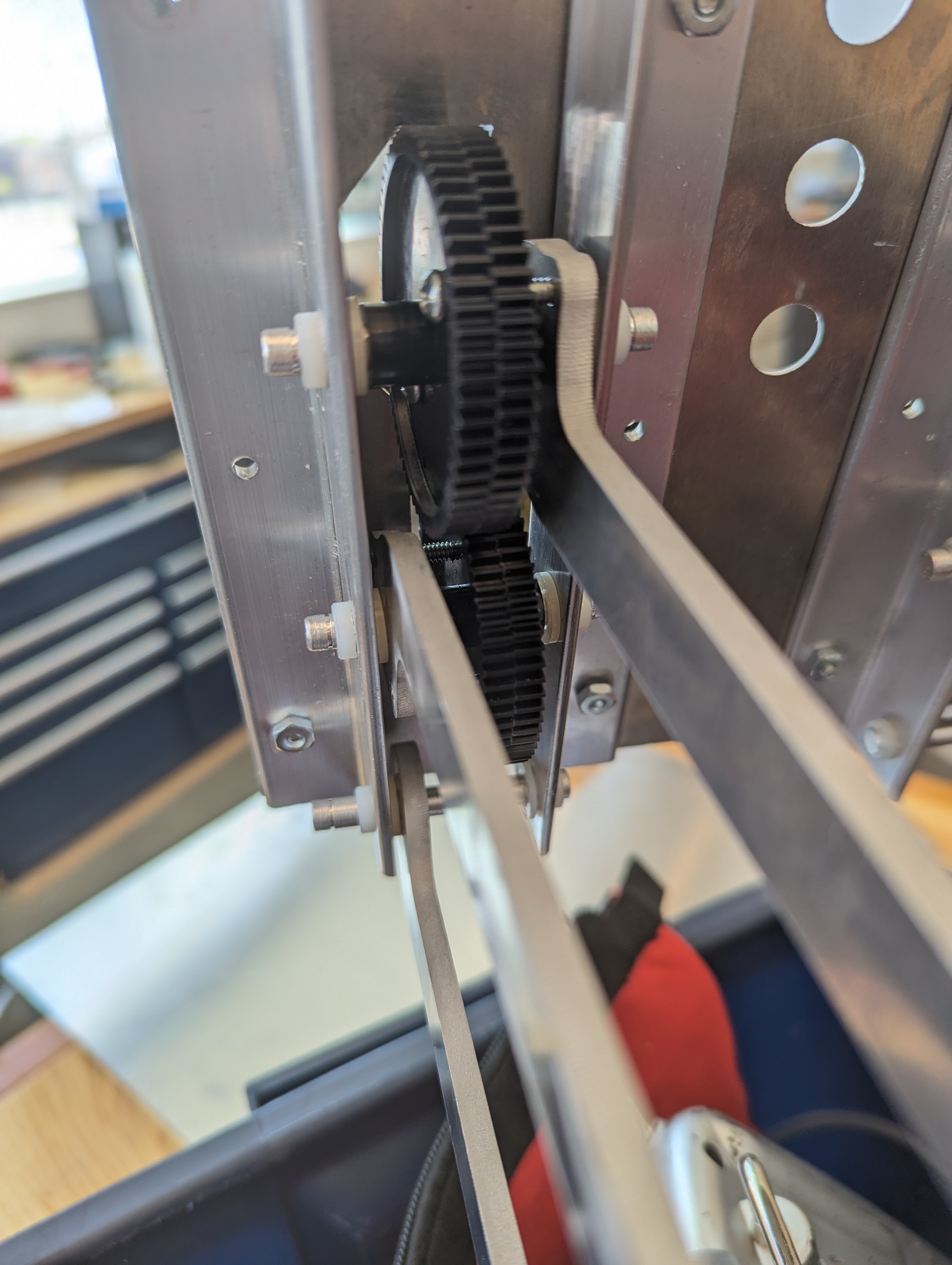
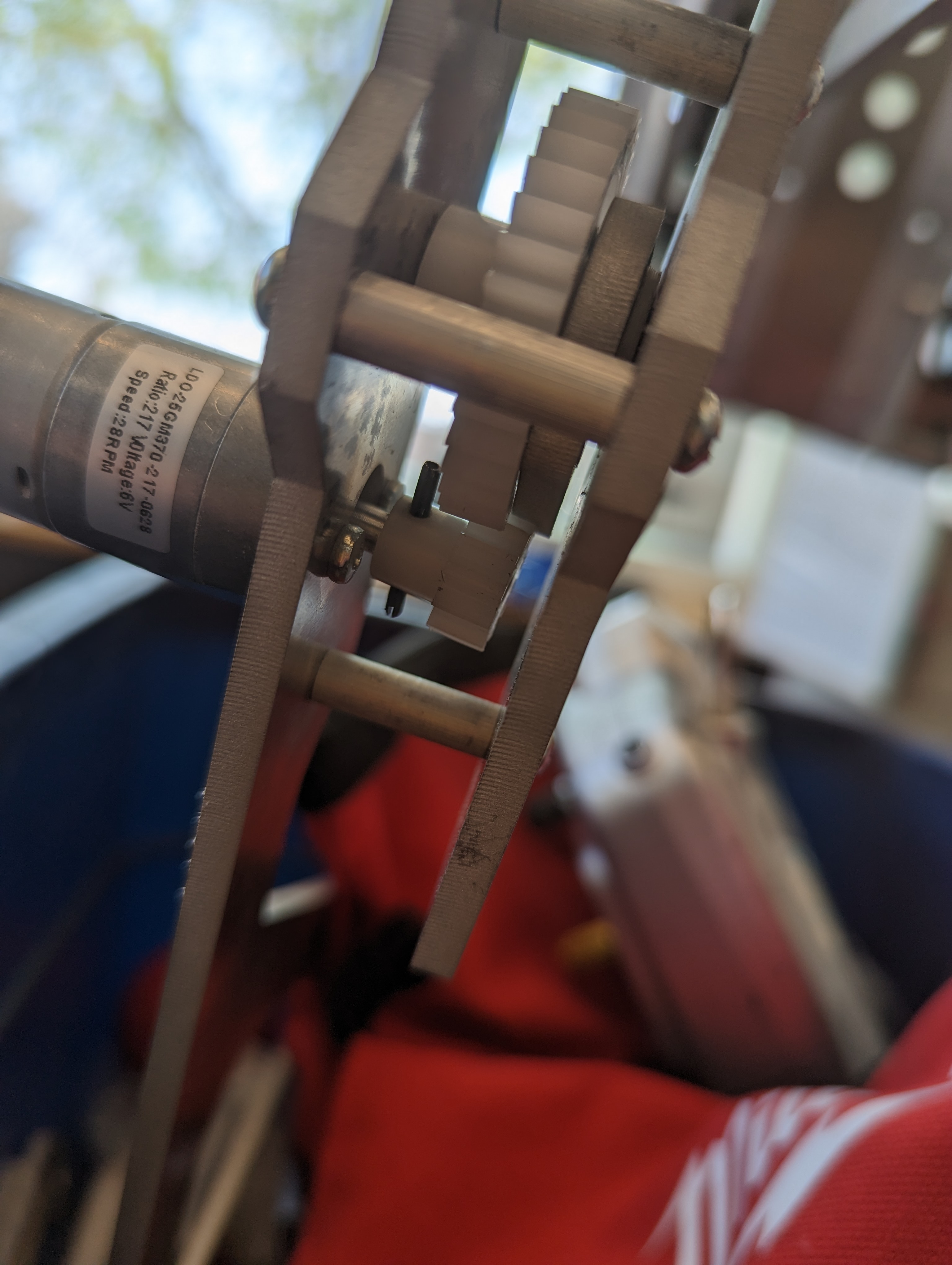
You can see in this image the tolerances weren't great on early revisions. Later versions cleaned this up so more of the gear tooth was used. Even further versions I would have likely doubled up the gear to spread out the force load.
Sprint to Finish
Cool, now I have to sprint to finish everything else in 2 weeks time, yikes. There's some schedules in my noteboook towards the end that draw out the rough implementation order, which goes generally as:
- Chassis and Drivetrain
- Winch
- Centrifuge Spinner
These are ordered in terms of necessity to final design. My robot can still get points through the DNA if it doesn't have a spinner, but it can't get points if it can't move.
Chassis and Drivetrain
I needed the chassis to be as stiff as possible since any flexing would interfere with the tight tolerances I needed elsewhere. It also needed to be easy to manufacture and quick to assemble and disassemble. I hit all the requirements to a reasonable degree, the only thing I would change if I were to do this again is to add stringer in the middle of the bot to stiffen that axis more than the 1/16in metal shelf did.
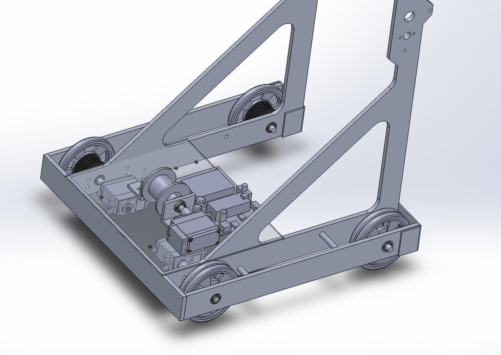
The drivetrain was a simple tank drive, meaning that the wheels on either side of the robot are attached together (like a tank). After making a timing belt of the correct size by cutting and sewing one back together, I did my first test:
Winch
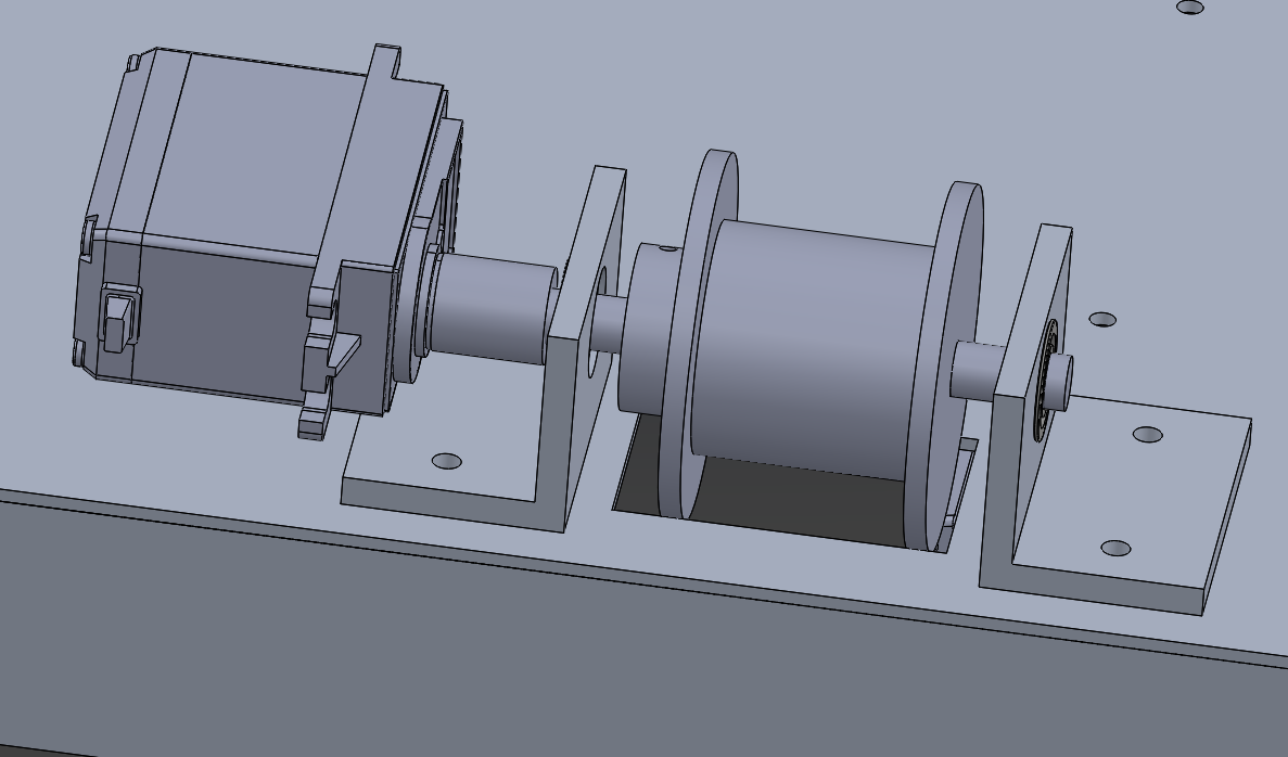
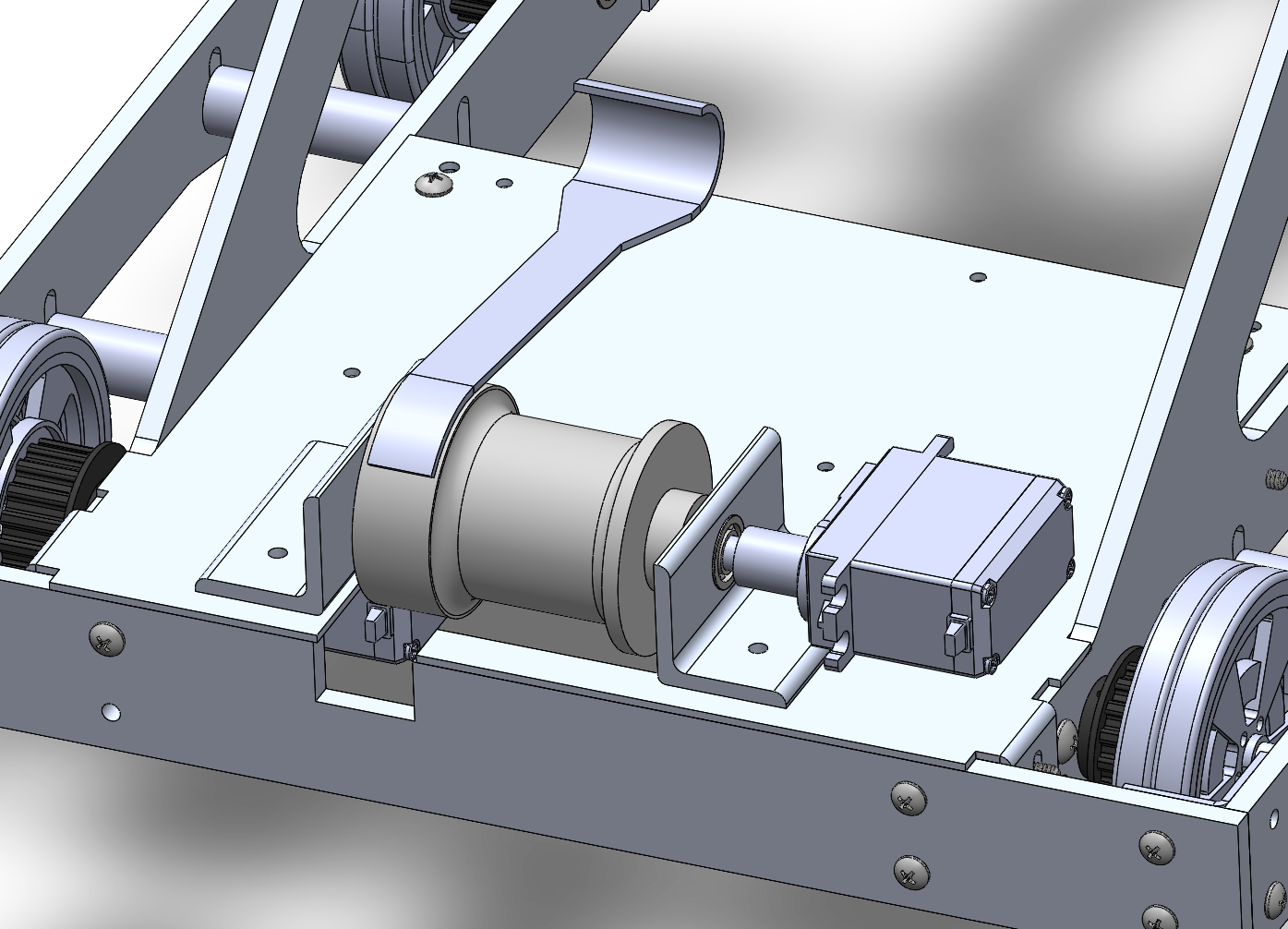
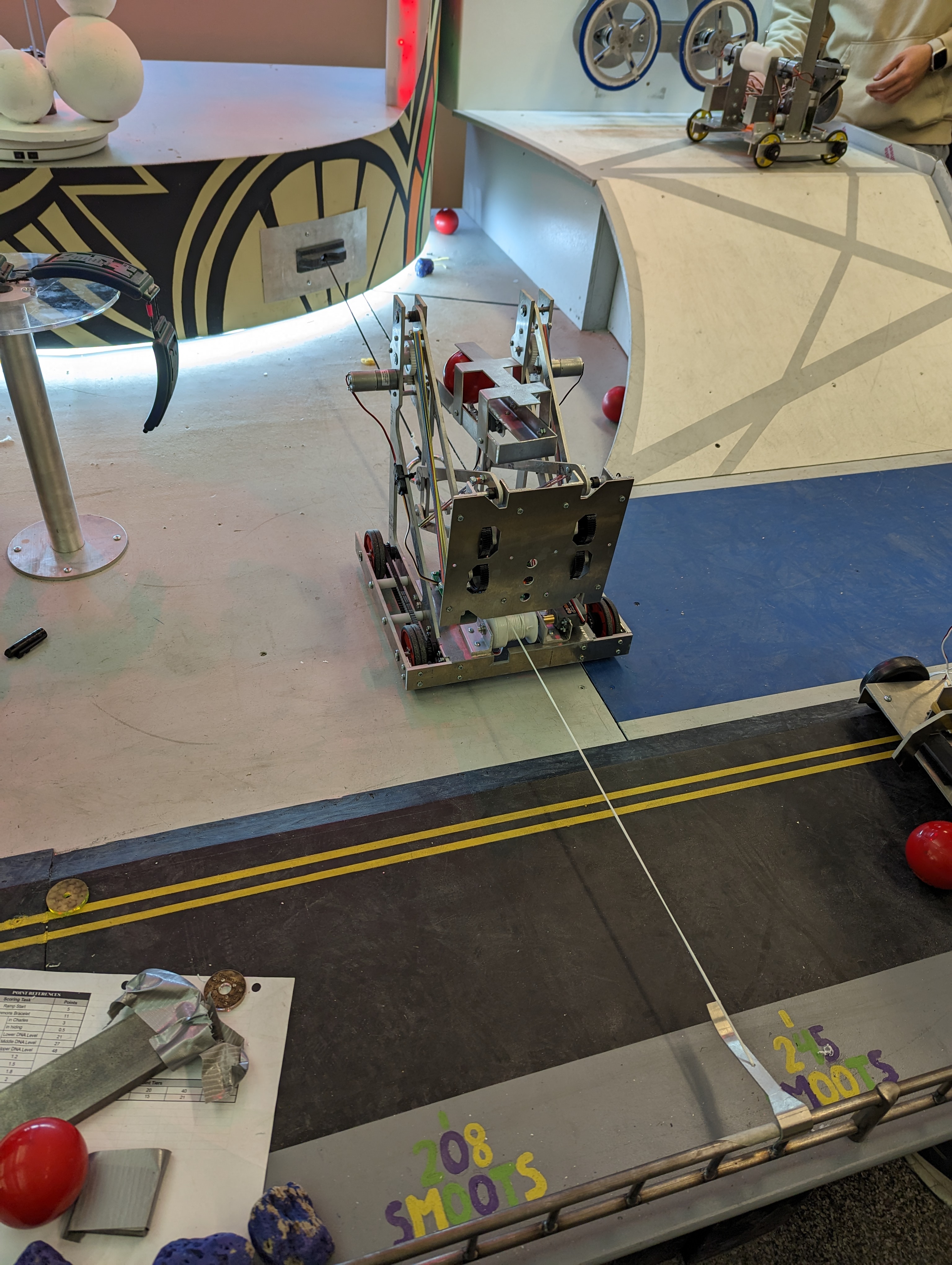
The winch's goal is to pull in the ring multiplier. Thankfully it was actually pretty easy to make. I had two L-backets support an axle and a servo which turned a spool made of turned Delrin. The spool was turned to the diameter calculated earlier in the Calculations section, and had a little area on the side which had some double sided sticky tape. This sticky tape would hold a hook made of bent sheet stock until the spool rotated the hook onto the railing, at which point it would detach. The hook that would grab the ring was just hung off of the front of the lift.
Spinner
From looking at the calculations earlier, it's clear that I need a lot of power to spin these centrifuges up to speed in a reasonable time. I only had 2 LDO motors left to work with based on all my previous design decisions, so I could do a spin up time of ~7 seconds, which honestly isn't bad. But the issue is that I'd have to make a gearing solution to combine the output of two motors, and I was running out of time. I CADed one anyways to see how simple I might be able to make it.
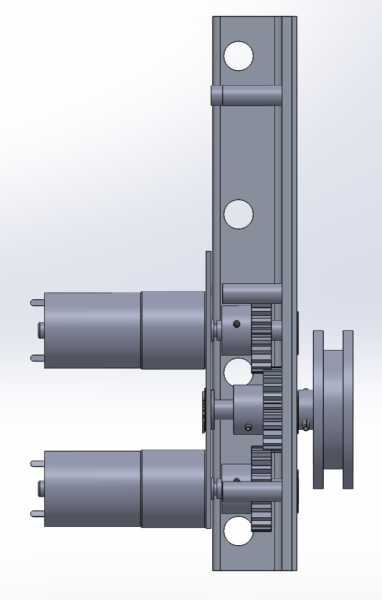
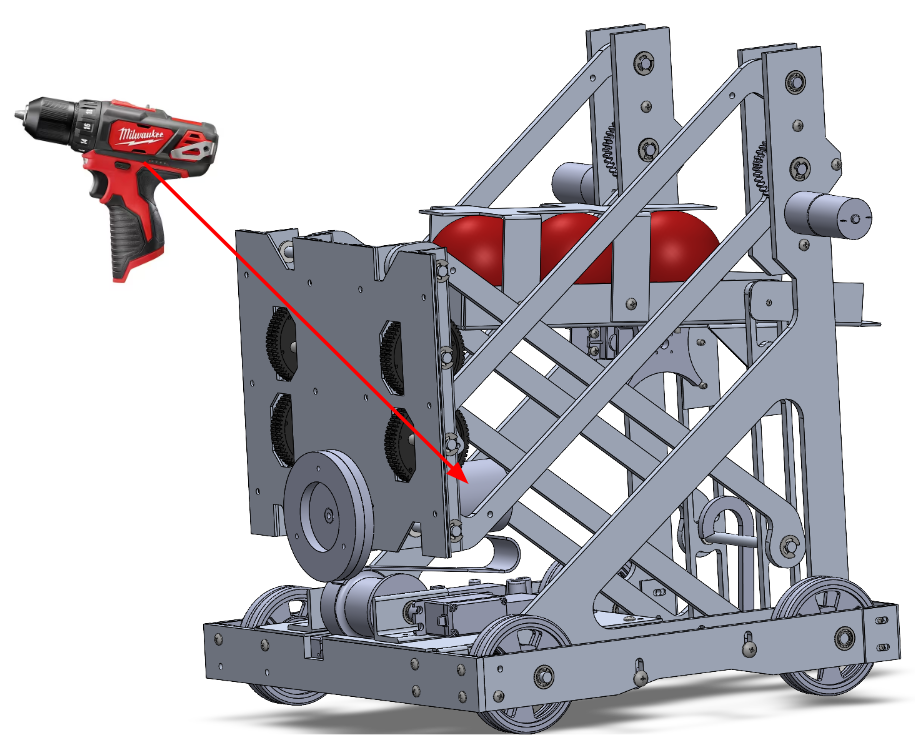
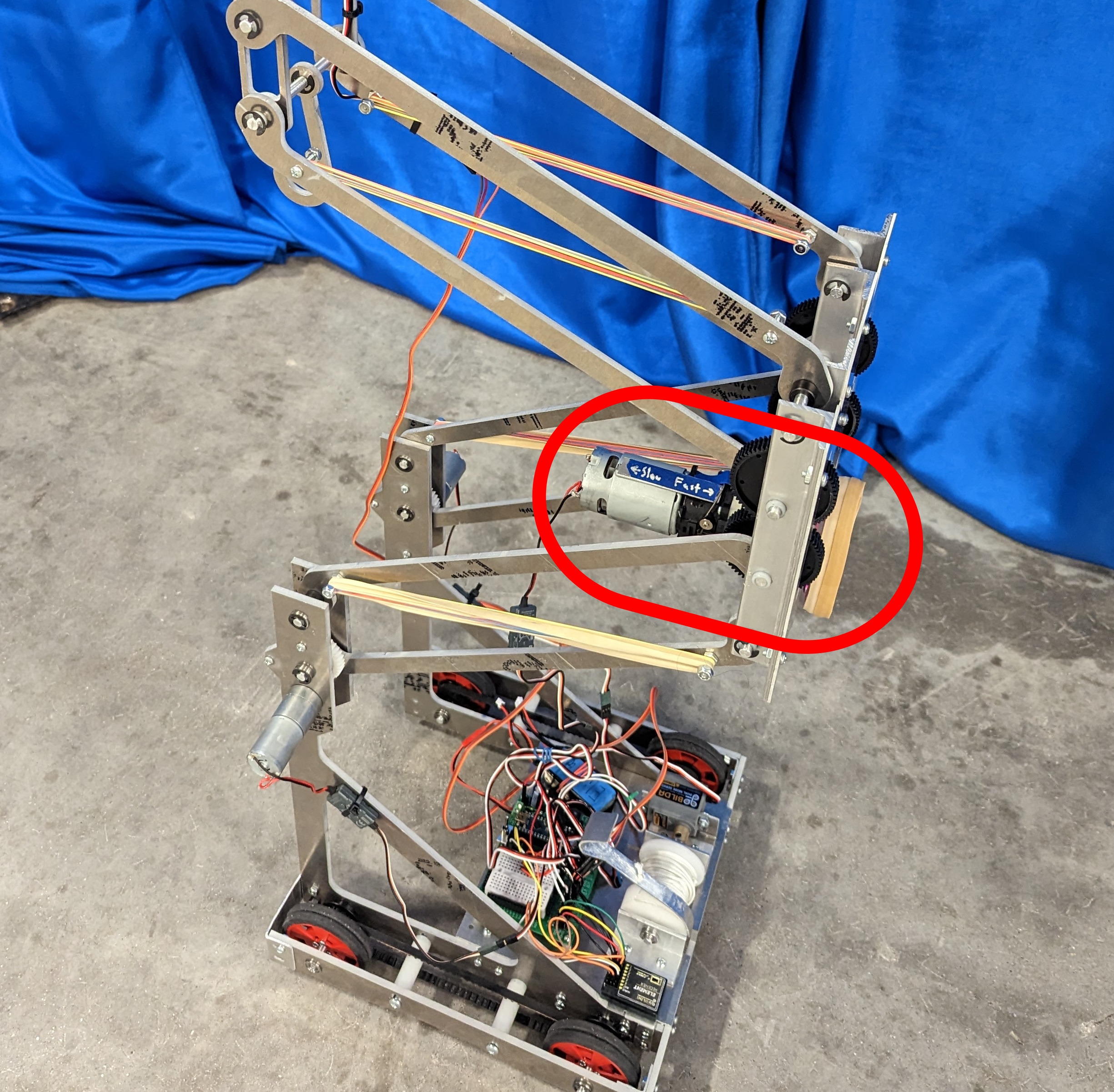
This is a lot of effort pinning those three gears, making the axles, and getting the tolerances nice. So, I gave a thought to a thing that had been hovering in the back of my mind for a while: We're allowed to use the full toolkit they gave us. This toolkit also included a cordless M12 Milwaukee drill. What if I took it apart and used the motor inside instead?
After much effort taking apart and reassembling the drill and learning how it worked, I managed to install it into my robot as the spinner motor.
Final Result
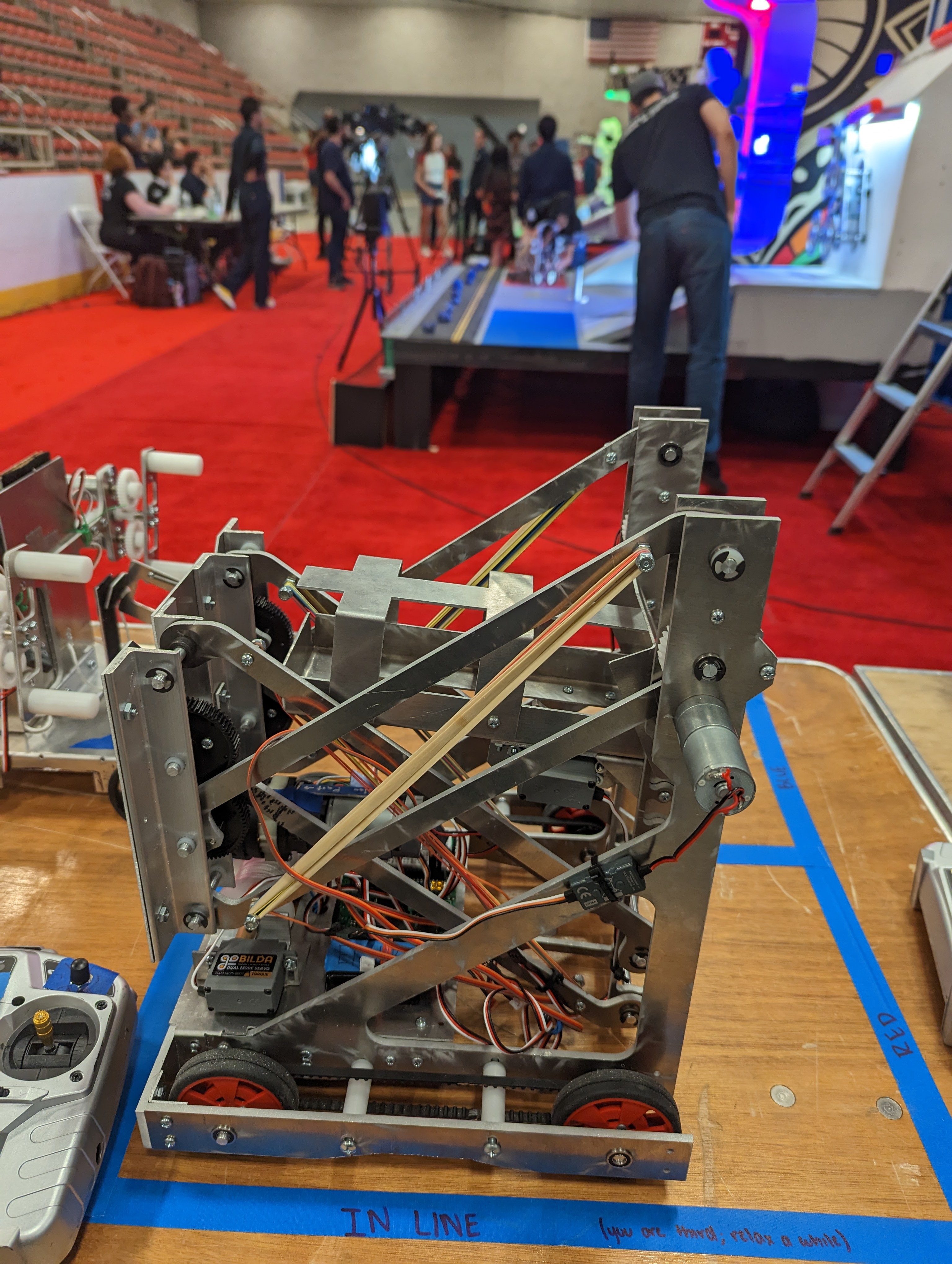
So now for the final results! Here's some shots and videos of what I ended up with in the end:
Photos
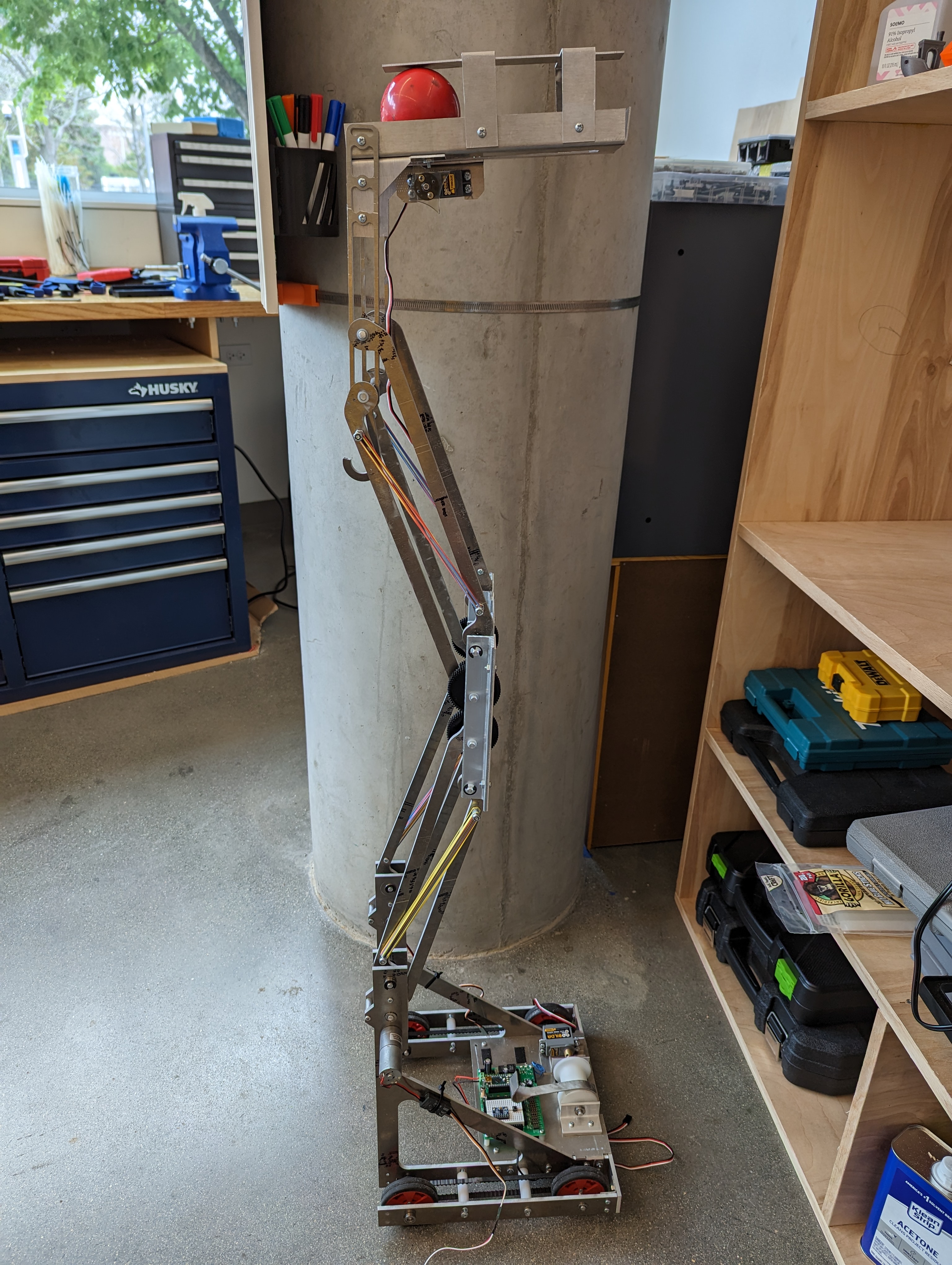
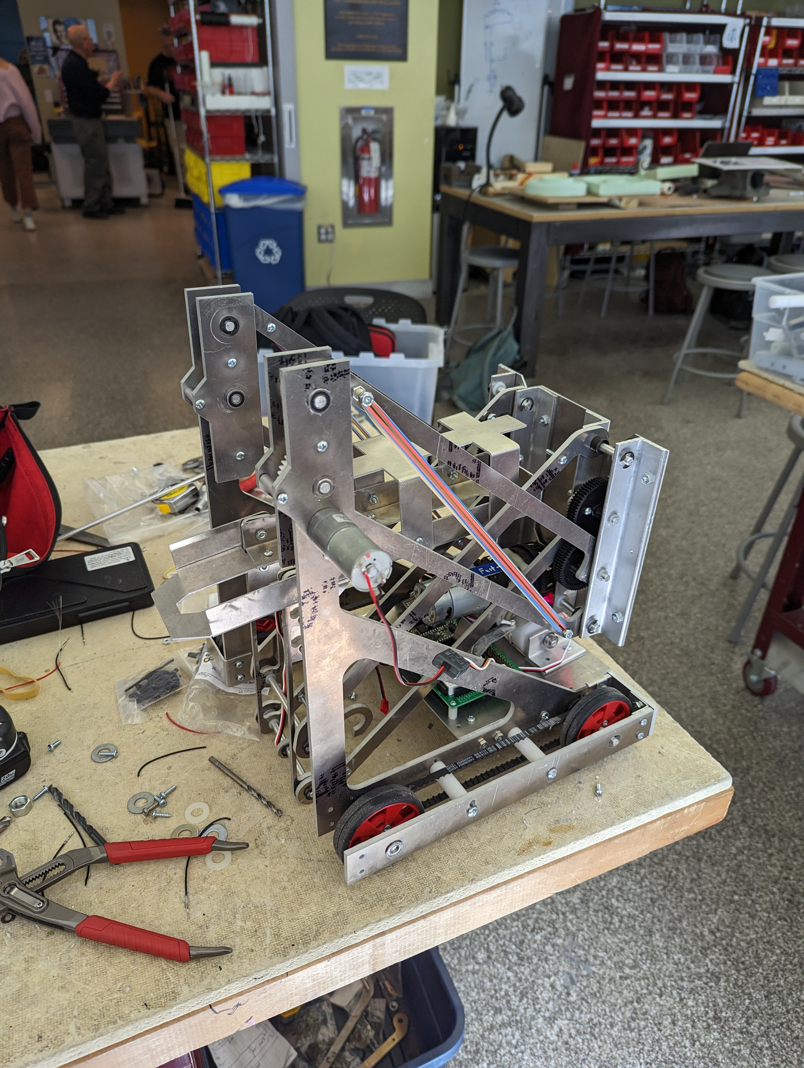
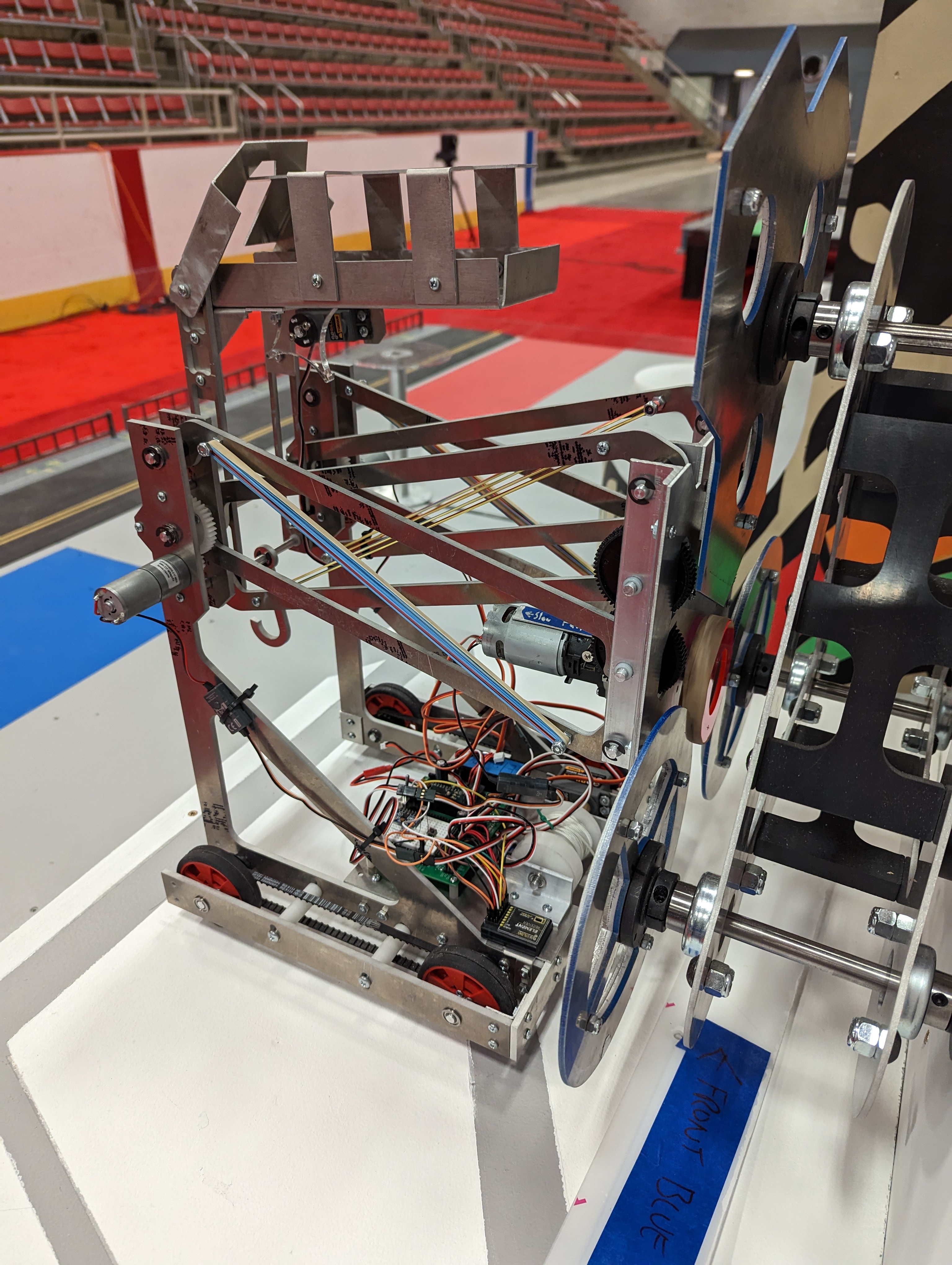
Videos
Competition Results
Now for the how it actually performed in the competition. As a bit of a preface, during the lead up to the competition, I was pulling all nighters constantly, so I was mentally a bit fuzzy on the day of competition. When eventually my turn comes, and I'm setting up my robot on the stage, my autonomous code activates when it's not supposed to. The lights from the stadium are bright enough to pass the threshold normally just my phone flashlight passes. So, I scramble to try to fix it live, and, tragically, wire a resistor to live instead of ground and fry my arduino and brick my robot. It haunted me for literal months afterwards, but I was consoled by the fact that the robot could actually do everything it was designed to do. I had built a working robot, just one that didn't at that crucial point.
Lessons Learned
Things to Improve
By far the biggest thing I learned was the importance of testing. Towards the end of the project I was way too focused on making improvements to small things I thought would cause issues than actually getting out in the field and testing. While the things I expected to cause issues might certainly do so, I learn far more per unit time actually seeing how the things I make perform than trying to guess before. This increased amount of testing would have been helped by sticking more strictly to a timeline and dropping things when I fall outside of the timeline. Also, I wish I had more time in the class, maybe precisely three weeks extra, so I didn't have to do everything in less time than was normal for the class, but that might just be an excuse for poor planning on my part. Prioritizing testing is the 80% of the things I would change if I were to do this class again.
This was the first time I had really used a lathe, and there were issues in my efficiency in manufacturing using the lathe. I built every lathe component as essentially its own separate part, which was a pain for all the little shafts with E-clip grooves, and standoffs with threaded ends. I should have done operations on a common shaft when possible, before parting into distinct parts.
I shouldn't have snapped some of the teeth off of the small gear on the lift motors. I didn't think the torque was high enough to break gears, I had assumed that the gears could be taken for granted. This could have been avoided by adding the rubber bands before testing or doubling up the width of the gears.
The cable management could have been better, sometimes the ball gate would unplug during testing, this could have been fixed trivially just by making correct length harnesses and zip tying them to the arms where needed.
Things done well
The MCM method was really useful. I think without it, I likely would have started working on the wrong subsystems of the robot first, and might have plowed on with my overly complex ball manipulator design. It was nice to identify the largest source of uncertainty early on and solve it, it worked to compartmentalize concerns. This is a design process I will try to adopt consciously in my future works.
Rapid prototyping methods and digital machining were extremely useful in decreasing iteration time. The lift wouldn't be possible to make if I had to remachine parts whenever I wanted to make a change.
Accounting for the tolerance issues was really useful. Inevitably, bending sheet metal by hand will have errors, so I tried to design the robot to account for these errors: holes became slots, and most parts became strictly 2D where possible. I also used some features for dual purpose, such as the standoffs near the drivetrain to also act as tensioners on the driving belt.
Given the limited resources we were allowed to use, getting creative with how I solved problems worked well. Some of my solutions were entirely unique to my robot and saved me a lot of time, effort, efficiency, or performance. These included the drill motor, tape hook, rubber bands, parallel ball gate, standoff tensioners, sewing belts, slotting holes, and use of compliant metal.
Overall, I learned how to make a really cool little robot!